Impulses dzherela life for teapots. Video about the preparation of the simplest impulsive building of living quarters. Merezhevy filter and vipryamlyach.
The sphere of stagnation of impulse blocks of life in the future is constantly expanding. Such dzherel zastosovyutsya for the living of all current and future and computer equipment, for the implementation of uninterrupted power supply dzherel, chargers for batteries of various applications, the implementation of low-voltage lighting systems and other needs.
In some situations, the purchase of a ready-made dzherel is not very pleasant from an economic or technical point of view, and folding an impulse dzherel with wet hands is the best way out of such a situation. Let this option be available and the availability of the current elemental base at low prices.
The most demanded at the pump is the pulsed dzherel with the living in the standard wire of the snake strum and the low-voltage output. Structural diagram such a dzherel is shown a little one.
Merezhevy vipryamlyach SV rework changing voltage life-giving line in the post and zdiisnyu zgladzhuvannya pulsation of the rectified voltage at the exit. The high-frequency conversion of the runway converts the rectified voltage into a changeable or unipolar one, which can form a rectangular pulse in the required amplitude.
They gave such a voltage, either without a middle, or after vibrating (VN) to go to the filter, which is smoothed, until the exit of which the tension is connected. The runway control is controlled by the control system, which takes the signal of the return signal from the direction of the vanishing.
Such a structure can be added to criticism through the appearance of dekilkoh lanes of transformation, which lowers the KKD of the dzherel. However, with the correct choice of the nasopharyngeal elements and the yaxic rosemary and the preparation of the uterine knots, the tension in the tension in the scheme of maliy, which allows us to take the real value of the KKD more than 90%.
Principal schemes of pulse blocks of life
Solutions of structural blocks include how to choose options for circuit implementation, and practical recommendations on the choice of the main elements.
For the straightening of the tether single-phase voltage, one of three classical schemes images for the little one:
- one-by-one period;
- zero (double period from the middle point);
- two-half-wave brukivka.
The skin of them is preoccupied by taman and nedolіki, yakі signify the sphere of congestion.
Single-Period Scheme surprised by the simplicity of implementation and the minimum number of conductor components. The main shortcomings of such a vibrator are the significant value of the pulsation of the output voltage (for a vibrating straightener, there is only one nap mesh tension) and a small coefficient of rectification.
Coefficient of rectification Kv depends on the average value of the voltage at the output of the rectifier Udk to the orderly value of the phase stranded stress Uph.
For a one-cycle circuit Kv = 0.45.
To smooth out the pulsation at the exit of such a straightener, you need a strained filter.
Zero, or two-period scheme from the middle point, even though the double number of rectified diodes, however, this little significant world is compensated by the lower equal ripple of the rectified voltage and the increase in the magnitude of the coefficient of rectification up to 0.9.
The main shortcoming of such a scheme for victoria in single-button minds is the need to organize the middle point of the tension of the wire, which transfers the presence of the wire transformer. The dimensions and dimensions of this mass are inconsistent with the idea of a small-sized self-contained impulse dzherel.
Dvuhnap_vper_odna bruk_vka scheme rectification can be shown for equal ripple and the coefficient of rectification, which is the zero scheme, but does not imply the obviousness of the hemstitch. Tse compensates for the head shortfall - the number of vipryamnyh diodes is doubled as a point of view of the KKD, so for the varty.
For smoothing the ripple of the rectified voltage to the best solutions of the victorious filter. Yoga zastosuvannya allows you to increase the value of the rectified voltage up to amplitude value mesh (at Uf = 220V Ufm = 314V). It is accepted to consider the lack of such a filter great values impulse streams and directing elements, but critical ones are not enough.
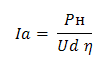
The choice of diodes is directly dependent on the value of the average straight struma Ia and maximum reversal stress U BM.
Taking the value of the pulsation coefficient of the output voltage Kp = 10%, we take the average value of the rectified voltage Ud = 300V. To improve the tension of the tension and the KKD of the HF conversion (80% is accepted for the rozrahunka, but in practice it is more visible, it is possible to take away the singing reserve).
Ia - the middle strum of the diode of the rectifier, pH-tension of the drive, η - CCD of the high-frequency converter.
The maximum reversible voltage of the rectifier element does not exceed the amplitude value of the tension of the rail (314V), which allows the component to be twisted with U BM =400V with a significant margin. You can beat discrete diodes, so you can also prepare vibrating bridges in different vibrators.
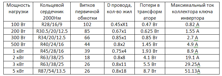
For safety, the specified (10%) pulsation at the output and directing the filter capacitor capacitance is taken from a 1 μF per 1 W output pressure. Electric capacitors are vikorated with a maximum voltage of at least 350V. Filter capacities for various strains are indicated at the table.

High-Frequency Converter: Its Functions and Circuits
A high-frequency switcher is a single-cycle or two-cycle key switcher (inverter) with a pulse transformer. Variants of HF conversion schemes are given a little.
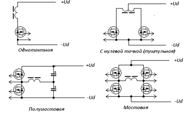
Single cycle circuit. At minimum quantity power elements and simplicity of implementation can be a little small.
- The transformer in the circuit works on a private hysteresis loop, which results in an increase in light expansion and overall tightness;
- For the prevention of exhaustion, it is necessary to take into account the significant amplitude of the impulse strum, which flows through the navprovidnikovy key.
The scheme is known to be the most congested in low-power outbuildings, depleting the significance of the smaller ones.
 To independently change or install a new license plate, you do not need special skills. Choose the right one to ensure the correct appearance of a calm stream and to promote the safety of home electrical services.
IN modern minds the provision of lighting as a middle ground, and on the streets of Dedali more often vicorist sensors are installed. Tse we give not only comfort and prosperity in our lives, but allow us to save money. Recognize practical reasons at the choice of installation location, connection schemes are possible.
Two-cycle circuit from the middle point of the transformer (push-pull). I gave my friend the name of the English version (push-pull) of the description of the robot. The scheme is valid in case of shortfalls in a single-cycle version, but it may be damp - the design of the transformer is complicated (it requires the preparation of identical sections of the primary winding) and promotion of the vimoga up to the maximum voltage of the keys. In another decision, merit for respect and widely zastosovuetsya in the pulse of life, which are prepared with their own hands and not only.
Two-stroke nap_bridge scheme. For the parameters, the circuit is similar to the circuit from the middle point, but does not depend on the folding configuration of the transformer windings. Vlasnym short circuit є need to organize the middle point of the filter vipryamlyach, scho causing some increase in the number of capacitors.
The reasons for the simplicity of the implementation of the scheme are the most widely used in pulsed power pipes up to 3 kW. At great strains, the variance of the capacitors of the filter becomes unacceptably high in pairs with the heater keys of the inverter and the most visible bridge circuit.
Two-stroke brukivka scheme. For the parameters it is similar to other two-stroke circuits, but the need for the creation of piece "midpoints" is relieved. Paying for the price of the plant, a number of power keys were built, which is a viable economic and technical point of dawn for stimulating the tight impulse dzherel.
The selection of the inverter switches depends on the amplitude of the collector jet (drain) I KMAX and the maximum pressure of the collector-emitter U KEMAH. For rozrahunka vikoristovuyutsya navantazhennia and coefficient of transformation of the pulse transformer.
However, first of all, it is necessary to repair the transformer itself. The pulse transformer is fixed on the core with a ferrite, permaloy or twisted in the ring of the transformer hall. For tightness up to 1 kW, a ferrite core of a ring or W-like type should be used as a whole. The transformer opening is carried out depending on the necessary tightness and the frequency of the transformation. To uniquely appear acoustic noise, the frequency of the conversion should be blamed for the intersonic range (more than 20 kHz).
If so, it is necessary to remember that at frequencies close to 100 kHz, the losses in ferite magnetic cores increase significantly. The design of the transformer itself is awkward and can easily be found in the literature. Actual results for various pressures and magnetic circuits are shown in the tables below.
Rozrahunok is broken down for a frequency of 50 kHz. Warning should be taken into account, that when working at a high frequency, the effect of winding the struma to the surface of the conductor, which can lead to a decrease in the effective winding, is possible. In order to avoid similar inaccuracies and reduce the cost of conductors, it is necessary to wind the winding from a few cores of a smaller cut. At a frequency of 50 kHz, the allowable winding diameter does not exceed 0.85 mm.
Knowing the tension of the voltage and the coefficient of transformation, it is possible to expand the strum at the primary winding of the transformer and the maximum strum of the power switch collector. The voltage on the transistors in the closed station is more vibrated, the voltage is lowered, so that the input of the HF-converter with a deakim reserve (U KEMAX = 400V). For these dates, a selection of keys is carried out. At the given hour best optionє victoria power transistors IGBT chi MOSFET.
For diodes that turn on the secondary side, it is necessary to trim one rule - their maximum operating frequency can override the frequency of the conversion. Otherwise, the KKD of the outwardly vipryamlyacha and the reversal of the flame will significantly decrease.
Video about the preparation of the simplest impulse life-support facility
In the article there are about impulsive blocks of life (given DBZH), as they have taken the widest zastosuvannya in all modern radio-electronic outbuildings and self-contained.
The basic principle of laying in the basis of the work of the DBZH is based in the converted mesh changeable voltage (50 Hertz) on the changed high-frequency voltage of a rectangular shape, as it transforms to the required values, straightens and filters.
The transformation is carried out for the help of hard transistors, which work in the key mode and pulse transformer, which at the same time establish the RF conversion circuit. If there is a circuit solution, then there are two possible conversion options: the first one - to follow the circuit of a pulsed self-oscillator, and the other - from the most advanced ones (to be used in most of the current radio-electronic attachments).
If the switching frequency is selected in the average range of 20 to 50 kilohertz, then the expansion of the pulse transformer, and also, the entire block of life, is minimized, which is an important factor for modern equipment.
Simplified scheme pulse changer to marvel below from the outrageous cherubs:
Turnover switch on transistors VT1 and transformers T1. Merezheva voltage through the mesh filter (SF) is supplied to the mesh vipryamlyach (SV), dewon it vibrates, is filtered by the filter capacitor Sf and through the winding of the transformer W1 T1 is fed to the collector of the transistor VT1. When applying the base of the transistor to a direct-current pulse, the transistor turns off and suddenly flows a growing stream of Ik. This stream will be passed through the winding W1 of the transformer T1, which will lead to the fact that the magnetic flux increases in the core of the transformer, when secondary winding W2 of the transformer is induced by EPC self-induction. It is possible for a positive voltage to appear at the output of the VD diode. When we change the trivality of the pulse applied to the base of the transistor VT1, the second lance will have a larger voltage, because the energy will increase more, and if we change the trivality, the voltage will change. In this way, by changing the trivality of the pulse of the base of the transistor, we can change the output voltages of the secondary winding T1, and also stabilize the output voltages of the PSU. The only thing for which is necessary is a scheme, how to form an impulse to launch such a keruvate time їх trivality (breadth). Like this circuit, the PWM controller is victorious. PWM - pulse-width modulation. To the warehouse of the PWM controller enter the generator of impulses, which sets (sets the frequency of the robot and the rotation), the circuits for protection, control and logic circuit, as well as for the trivality of the impulse.
To stabilize the output voltages of the DBZH, the PWM circuit of the controller "can know" the magnitude of the output voltages. For these purposes, there is a lanyard of a stiffness (or a lanyard of a pivotal link), a loop on the optocouplers U1 and resistors R2. The increase in the voltage at the secondary lance of the transformer T1 was brought to an increase in the intensity of the vibration of the light, and then, the support for the phototransistor junction was changed (to enter the warehouse of the optocoupler U1). In my line, I created a voltage drop on the R2 resistor, which is successively switching on the phototransistor and changing the voltage on the output of 1 PWM controller. Changing the voltage changes the logical circuit that enters the warehouse of the PWM controller, to increase the trivality of the impulse, until the voltage on the 1st output does not match the set parameters. When the voltage is changed, the process is reversed.
At BDZh zastosovuyutsya 2 principles for the implementation of lances of the degree - "without middle" and "indirect". More than descriptions, the method is called "without middle", so that the voltage of the turning link is taken without middle from the secondary straightener. In the case of indirect stiffening, the voltage of the turning link is taken from the auxiliary winding of the pulse transformer:

Changing or increasing the voltage on the W2 windings, causing the voltage to be changed on the W3 windings, as well as applied through the R2 resistor until the 1 PWM controller is installed.
With a lance, I think we have sorted it out, now let's look at this situation as a short chime (KZ) in the adventurous DBJ. In this way, all the energy that is seen in the second lances of the DBZH will be destroyed and the output voltage is practically equal to zero. As a rule, the circuit of the PWM controller is energized to increase the trivality of the pulse in order to raise the voltage level to the required value. As a result, the transistor VT1 will be more and more rebuvat at the critical station, and through the new one the strum will increase, which will flow. I’m sorry, I’ll bring it to the end of the operation of the transistor. In the DBZH, the switch of the transistor was switched over to the shift of the stream in such non-standard situations. The basis of її to become the resistor Rzasch, inclusions in series in the lance, which flows through the strum of the collector Ik. An increase in the flow of Ik flows through the transistor VT1, resulting in an increase in the voltage drop on the resistor, and, also, the voltage that is applied to the display of 2 PWM controllers will also change. If the voltage drops to the level equal to the maximum allowable stream of the transistor, it is logical for the PWM controller circuit to attach the pulse formation to the output of the 3rd block of life, to switch to the shutdown mode or, in other words, turn it on.
At the end, those would like to describe in a report the achievements of the DBZH. As it was already guessed, the frequency of the pulsed switch is high, at the connection, the dimensions of the pulse transformer are changed, and therefore, as it does not sound paradoxical, the variability of the DBZH is less than the traditional BP, the shards are less than the metal on the magnetic conductor and navit not unimportantly to those that the number of details in the DBZh is greater. Another one of the advantages of the DBZH is small, in the case of a superior power supply unit, the capacitance of the filter capacitor of the secondary rectifier. The change in capacity has become possible for the increase in frequency. І, nareshti, KKD of the impulse block of life is 85%. It is connected with the timing that BDZh saves energy electric lines only a short time of the open-circuit transistor is turned over, when the energy is closed, the energy is charged for the discharge of the filter capacitor of the secondary lance.
To the minus, one can see the aggravation of the DBZH scheme and the increase in the impulse changeovers of the DBZH itself. The improvement of the changeover is due to the fact that the transistor is working in the key mode. In such a mode, the transistor has a pulsed transition, which blames the moments of the transition processes of the transistor. Tse є nedolіkom be-like a transistor, which works in the key mode. However, if the transistor works with small voltages (for example, transistor logic with a voltage of 5 volts), it’s not scary, our voltage is applied to the collector of the transistor, to become approximately 315 volts. To combat these transitions in DBZH, folding schemes of mesh filters are used, lower for the sizable BP.
Invisible part of the skin computer living block (BP). Vіn important yak і, yak і іnshі parts of the computer. When buying a block of life, it is rare to finish it, so that a good power supply unit can provide life for many generations of systems. Vrakhovuchi all tse before the arrival of the block of life, it is necessary to put even more seriously, the computer's share of the computer is directly deposited in the work of the block of life.
Mainly recognized by the living block -life force forming, which is necessary for the functioning of all PC blocks. The main voltages of living components:
- +3.3V
Іnuyut so dodatkova voltage:
For zdіysnennya galvanic decoupling It is sufficient to prepare a transformer with the necessary windings. Ale for the life of the computer needs a chimala tightness, especially for current PC. For computer life I would have had a chance to prepare a transformer, which maw bi is not only a great expansion, but also richly important. However, for increasing the frequency of the struma of the transformer, for the creation of the same magnetic flux, less turns and fewer cuts are required for the magnetic circuit. In blocks of life, based on the conversion, the voltage frequency of the transformer is 1000 and more times higher. This allows you to create compact and light living blocks.
The simplest impulse power supply
Let's look at the block diagram of a simple pulse block what lies at the basis of all impulse blocks of life.
.
The first block is created transformation of the change in the tension of the rope on the post. Such reworking folded from a diode bridge, which directs the changing voltage, that of a capacitor, which smooths out the pulsations of the rectified voltage. This boat also has additional elements: voltage filters in the pulse generator pulses and thermistory for smoothing the jet stream at the moment it is turned on. However, these elements can be daily with a method of saving on co-variation.
The next block - pulse generator, which generates pulses with a singing frequency, to live the primary winding of the transformer. The transformer performs the main functions of the live block: galvanic isolation with a barrier and voltage reduction to the required values.
The voltage is changed, which is taken from the transformer, the offensive block is converted to a constant voltage. The block is made up of diodes that rectify the voltage and the pulsation filter. In the first block, the pulsation filter is richly folded, in the first block, it is folded from a group of capacitors and chokes. In a cost-saving way, virobniki can install low-capacity capacitors, as well as low-inductance chokes.
pershy pulse block being two-stroke or single-stroke reversing. Two-stroke means that the generation process is composed of two parts. In such a transformation, two transistors are curved and curved. Vidpovidno in a single-cycle conversion, one transistor vibrates and closes. Schemes of two-cycle and single-cycle conversion are presented below.
.
Let's look at the elements of the scheme.
X2 - Rose of the living scheme.
X1 - rose from what the output voltage is.
R1 - opir, which asks for a little bit on the keys. It is necessary more than a stable start-up of the process of splitting in a converting machine.
R2 - opіr, which is between the strum of the base on transistors, which is necessary for the protection of transistors from the fire.
TP1 - The transformer has three groups of windings. The first output winding forms the output voltage. Another winding is for transistors. Third form strong voltage for transistors
At the first moment of switching on the first circuit, the transistor is three times critical, so that a positive voltage is applied to the base through the resistor R1. A stream flows through the output transistor, which also flows through the II winding of the transformer. Strum, which flows through the winding, creates a magnetic field. The magnetic field creates a voltage in the other windings of the transformer. At the result of the winding III, a positive voltage is created, as if the transistor is turning even more. The process is being done, the docks of the transistor cannot be consumed in the saturation mode. The power mode is characterized by the fact that the increase in the applied control jet to the transistor leaves the jet permanently.
So, as the voltage in the windings is generated only at the time of a change in the magnetic field, its growth or fall, the current growth of the struma at the output of the transistor, also, before the emergence of EPC in the windings II and III. The increase in voltage in the winding of the III drive is up to the change in the stage of the transistor. The output stream of the transistor will change, and the magnetic field will change. The change in the magnetic field caused the tension to equalize the opposite polarity. Negative voltage in the winding III is more likely to turn off the transistor more. Process trivatime doti, magnetic field docks do not appear again. If the magnetic field is low, the negative voltage in the winding III is also high. The process will be repeated again and again.
The two-stroke transformation works for this very principle, but there is a difference in the fact that there are two transistors, and the stench of the devil is twisted and curled up. That is, if there is one omission, another omission. The scheme of a two-stroke switcher can be of great importance, as it is the whole loop of the hysteresis of the magnetic conductor of the transformer. Vykoristannya odnієї dіlyanki hysteresis loops or magnetization only in one directly lead to the vindication of many negligible effects, yakі reduce KKD rework and improve its characteristics. To this, basically, a double-ended circuit is converted with a phase-shifting transformer. In schemes, where simplicity is needed, small dimensions, and small tightness, all the same, a single-cycle scheme wins.
Blocks of life to the ATX form factor without correction of the pressure coefficient
Reworking, looking at it, even if it’s completed, but in practice it’s hard to beat them. The frequency of the changeover, the change in voltage and many other parameters “float”, change depending on the change: the voltage of life, the change in the change of temperature. As well as using the keys to handle the controller, which is the moment to improve stabilization and various additional functions, then you can create a scheme for living outbuildings. The scheme for the block of life from the shutdown of the PWM controller is simple, і, zagal, є by a pulse generator, prompted by the PWM controller.
PWM - pulse width modulation. It allows you to regulate the amplitude of the signal of the last low-pass filter (low-frequency filter) with a change in trevalosity or sparring of the impulse. Golovnі perevagi ShІM tse high value of KKD pіdsilyuvachіv tightness and great possibility of zastosuvannya.

A scheme is given for the block of life, it can be a little tightness and it is like a victorious key polovy transistor, which allows you to ask the scheme and get additional elements necessary for management transistor switches. IN high pressure living blocks PWM controller maє elementi keruvannya ("Driver") with the external key. IGBT-transistors are used as the keys in the life blocks of great tension.
Merezhev's voltage in this circuit is transformed into a constant voltage and through the key it goes to the first winding of the transformer. The other winding is used for the life of the microcircuit and the formation of the voltage of the return link. The PWM controller generates pulses with a frequency, as set by the RC-lance, connected to the bottom 4. The pulses are fed to the input of the key, whichever is possible. Trivality of impulses changes in a fallow manner depending on the stress on the bottom 2.
Let's take a look at the real scheme of the ATX block. There can be more elements and in my presence addendums. With chervonim squares, the scheme of the living block is mentally divided into the main parts.
Scheme ATX power supply unit 150-300 W
For the life of the microcircuit of the controller, as well as the formation of the +5 voltage, it is like a computer, if the fault is turned off, the circuit has one more changeover. On the scheme, the values are shown as block 2. As you can see, the faults are behind the scheme of a single-cycle changeover. The other block has additional elements. Basically, there are voltage splashes, which are generated by a transforming transformer. Microcircuit 7805 - voltage stabilizer forming a draft voltage + 5V from the rectified voltage of the converting device.
In most cases, in the block for forming the chergovoi voltage, non-standard or defective components are installed, which reduce the frequency of the transducer to the sound range. After that, there is a little squeak from the block of life.
Oskіlki block of life live in the yard of the snake voltage 220V, And the reworking will require life with a constant effort, the power needs to be recreated. The first block zdіysnyuє vipryamlennya and filtratsіyu zmіnnoї merezhovoї narug. This block also has a filter for the override, which is generated by the live block itself.
The third block is a PWM controller TL494. Vіn zdіysnyuє all the main functions of the block of life. Protects the live block from short flickers, stabilizes the voltage and forms a PWM signal for controlling transistor switches, as if it is being fed to a transformer.
The fourth block consists of two transformers and two groups of transistor switches. The first transformer forms the voltage for the output transistors. Oscilki PWM controller TL494 generates a signal of low intensity, the first group of transistors strengthens the signal and transmits it to the first transformer. Another group of transistors, or else, is driven onto the main transformer, which forms the main voltages of life. Such a foldable circuit for controlling external keys is designed through the foldable control of bipolar transistors and the protection of the PWM controller high voltage.
The fifth block is composed of Schottky diodes, which rectify the voltage of the transformer, and the low-pass filter (LPF). The low-pass filter is composed of electrical capacitors with a significant capacity and throttles. At the output of the low-pass filter, there are resistors, like navantage yoga. Qi resistors are necessary in order to ensure that after the switching capacity of the living block is not overcharged. So the resistors stand and at the output vipryamlyacha voltage.
Reshtu elements, which are not circled in the block of the lance, are formed " alarms". Tsimi lances zdіysnyuєtsya robot zakhistu bloc zhivlennya vіd short hum or control of the correctness of the output voltage.
Now we wonder, like on a different board power supply unit 200 W mixed elements. The little one shows:
Capacitors that filter out the output voltage.
The place is not soldered capacitors in the filter of the output voltage.
Coils of inductance, which measure the filtering of the output voltage. The larger cat plays the role of a filter, and the other works as a ferromagnetic stabilizer. Tse allows troch to reduce the distortion of the voltage at uneven ambition free external voltages.
Microcircuit PWM stabilizer WT7520.
Radiator on which Schottky diodes are installed for voltage +3.3V and +5V, and for voltage +12V zvichaynі diodes. Often, especially in the old blocks of living, on which radiators are placed additional elements. The elements of voltage stabilization + 5V and + 3.3V. IN modern blocks zhivlennya rozm_shchuyutsya on tsomu radiator and diodi Schottky for all the main voltages or field transistors, like vikoristovuyutsya as a directing element.
The main transformer, which forms the formation of all voltages, as well as the galvanic connection with the mesh.
A transformer that forms a keruyuchu voltage for the output transistors.
Converter transformer, which forms a draft voltage + 5V.
Radiator, on which location the transistors are turned, as well as the transistor is turned into a worm-shaped voltage.
Voltage filter capacitors. Їх not obov'yazkovo may be two. For the formation of a bipolar voltage and the resolution of the middle point, two capacitors of equal capacity are installed. The stink to dilyat straightened the mesh stress navpil, by the same time forming two stresses of different polarity, connected at the central point. In circuits with unipolar life, there is only one capacitor.
Elements of the filter measure the type of harmonics (shift code) that are generated by the live block.
Diode of the diode bridge, which zdіysnyuyut vipryamlennya zmіnnoї pripruzі merezhi.
Living unit 350 W power is equivalent. At the same time, you fall into the vіchі great rozmіrіv board, zbіlshenі radiators and a larger rіzmіru transforming transformer.
Output voltage filter capacitors.
Radiator, which cools diodes, which rectifies the output voltage.
PWM controller AT2005 (analogue of WT7520), which stabilizes the voltage.
The main transforming transformer.
Transformer that forms the voltage for external transistors.
Transformer for converting the draft voltage.
Radiator that cools down the output of the transistors.
Voltage filter in the blocks of life.
Diode bridge.
Voltage filter capacitors.
For a long time, the outlined scheme was stagnant at the blocks of life and at the same time it was stunned.
Blocks of life to the ATX format with the correction of the pressure coefficient
In the case of looking at the schemes for the purpose of the merezhi, a capacitor is used, which is connected to the merezhі through a diode place. The charge of the condenser is only felt in that case, for example, the voltage is less for the thread. As a result, the strum is impulsive in nature, which may be impersonal short-lived.
Pererahuemo tsі nedolіki:
- strums to bring in more harmonics (pereshkodi) at the merezha;
- the amplitude of the struma is large;
- significant reactive storage jet;
- the net tension does not vibrate for a long period;
- The CCD of such schemes can be small.
New living blocks I can improve the current scheme, it has one more additional block - tension coefficient corrector (KKM). Vіn zdіysnyuє pіdvishchennya kofіtіtsієnta natuzhnostі. Abo more my simple tidy up some of the shortfalls of the bridge vipryamlyacha voltage.
S = P + jQ
The formula for total tightness
Coefficient of tension (KM) characterizes the degree of tension in active warehouse and reactive tension. In principle, one can say, but now it’s safe reactive tension, it’s obvious and not greed.

It is permissible that we have some kind of attachment, a living block, with an intensity coefficient of 0.7 and an intensity of 300 watts. It can be seen from rozrakhunkiv that our block of life is constantly strained (the amount of reactive active tension) more, lower assigned to new. І tsiu potency can be given a measure of life 220V. If you want this tension, you don’t have to bear it (navit the electrician її not fixing) it’s still there.
That is why the internal elements and the mesh darts can be ripped for 430 watts, not 300 watts. And to show one’s own symptoms, if the coefficient of tension is more than 0.1 ... Through this, the city’s network is fenced with vicorist, with a coefficient of tension less than 0.6, and if such a coefficient of tension is less than 0.6, a fine is imposed on the sergeant.
Clearly, the campaigns have spawned new schemes for blocking livelihoods, similar to the KKM. On the other hand, like a KKM, there were inclusions at the input of a high inductance inductor, such a live block is called a live block with PFC or a passive KKM. A similar block of life can move KM. In order to reach the required CM, it is necessary to equip the life blocks with a large throttle, so that the input support to the life block has an imaginary character through the installed capacitors at the output of the rectifier. Installing a throttle significantly increases the weight of the block of life, and raises the KM to 0.85, which is not so rich.
Throttle adjustment for KM correction
Lastly not high efficiency passive KKM in block zhivlennya a new scheme of KKM was introduced, as it was inspired on the basis of PWM-stabilizer, wound on a choke. Tsya scheme to bring impersonal pluses to the block of life:
- expansion range of operating voltages;
- it became possible to significantly change the capacitance of the voltage filter capacitor;
- significant advancement of KM;
- change masi to the block of life;
- zbіlshennya KKD to the block of living.
Є th nedolіki tsієї schemes - tse decrease in the reliability of the BP that is incorrect robot with deakimi dzherelami uninterrupted life I'm with the switching modes of the robot and the battery/merezha. Incorrect operation of the circuit diagram with DBZh viklikan Tim, that the scheme has actually decreased the capacity of the firring voltage filter. At the moment, if the voltage is lost for a short time, the strum of the KKM is greatly increased, the necessary voltage boost at the exit of the KKM, as a result, there is a spratsovuє zakhist in the form of a short circuit (short flicker) in the DBZh.

If you marvel at the circuit, then there is a generator of impulses, which is a kind of induction on the throttle. Merezhev, the voltage is rectified by a diode bridge and is supplied to the key, driven by an L1 choke and a T1 transformer. The transformer of introductions zvorotny zv'yazok of the controller with a key. The voltage from the choke is taken for additional diodes D1 and D2. Moreover, the voltage is increased by the help of additional diodes, then from the diode bridge, then from the inductor, and charging the capacitors Cs1 and Cs2. The key Q1 is turned off and in the throttle L1 the energy of the required value is accumulated. The volume of accumulated energy is regulated by the trivality of the key that has been opened. The more accumulated energy, team more voltage please choke. After the key is switched on, the energy accumulated by the inductor L1 through the diode D1 is transferred to the capacitors.
Such a robot allows you to reverse the entire sinusoid of the variable voltage on the input of circuits without CMC, and also to stabilize the voltage to live the conversion.
Current block diagrams often get stuck dual channel PWM controllers. One microcircuit zdіysnyuє to the robot as a reworking, so і KKM. As a result, the number of elements in the scheme of the living block is reduced.
Let's look at the scheme simple block 12V power supply from the ML4819 dual-channel PWM controller. One part of the living block stabilized voltage+380V. The second part is the conversion, which forms a permanently stabilized voltage + 12V. KKM is folded, as it is more considered once, from the key Q1, the inductor L1 of the transformer T1, wound by it, is a zvorotny zv'yazok. Diodes D5, D6 charge capacitors C2, C3, C4. The switch is made up of two keys Q2 and Q3, mounted on the T3 transformer. impulse voltage rectified by a diode folding D13 and filtered by an inductor L2 and capacitors C16, ° C18. Behind the help of the U2 cartridge, a voltage regulation of the output voltage is formed.

Let's take a look at the design of the living block, in which there is an active KKM:
- Fee management strumovym zakhist;
- Throttle, which plays the role of a voltage filter +12V and +5V, and the function of group stabilization;
- Throttle filter voltage + 3.3V;
- Radiator, on which the external voltage diodes are placed;
- head converting transformer;
- Transformer, using the keys of the head switch;
- Transformer of an additional turn-over (which forms a draft voltage);
- Payment for the controller of the correction coefficient of the tension;
- Radiator, which cools the day and the key of the head switch;
- Filter voltages in the overflow code;
- Throttle of the corrector of the coefficient of tension;
- Voltage filter capacitor.
Design features and types of roses
Look at see roses, which can be present on the block of life. On the back wall of the living block available roses for connection mesh cable that vimikach. Previously, it was ordered from the rose of the tethered cord to the same rose for connecting the tethered cable of the monitor. Optionally, there may be other elements:
- indicators of the voltage of the measure, otherwise I will become a worker of the block of life
- Buttons for turning off the robotic fan mode
- button for switching the input tethered voltage 110/220V
- USB ports built into USB hub life block
- else.

On the rear wall, all the fans should be installed, which are blown out of the air conditioning unit. The fan bowls are located at the upper part of the living unit through a larger space for installing the fan, which allows you to install a large and quiet active cooling element. On some blocks of life, two fans are installed, one in the top and one in the back.

exit from the front wall wired with a rose. Some living blocks, modular, wines, like and other darts, are connected through a socket. Below it is indicated on the little one.

You can remember what skin tension can have your own color:
- Yellow color - +12 V
- Red color - +5 V
- Orange color - +3.3V
- Black color - scorching or earth
For other strains, the color of the darts in the skin vibrator can be changed.
On the little one, the roses of the additional life of the video cards are not shown, the stink shards are similar to the rose of the life of the processor. Also, they use other types of roses, which are used in the computers of the company's choice of companies DelL, Apple and others.

Electrical parameters and characteristics of living blocks
The living unit has a lot of electrical parameters, most of which are not indicated in the passport. On the side sticker of the living block, it sounds only a few of the main parameters - the working voltage and tension.
Pressure on the block of life
Tension is often indicated on labels great font. The pressure of the power block, characterizes, how many wines can supply electrical energy to accessories that are connected to a new one (motherboard, video card, hard disk and other).
According to the idea, to add up to the summation of vicorous components and choose the block of life of the troch of greater tension for the reserve. For pidrahunku puffiness fully suitable recommendations assigned passport has a video card like this, the thermal package of the processor, etc.
But really, everything is richly folded, so that the block of life has different voltages - 12V, 5V, -12V, 3.3V and other. The skin line of tension is protected for its tightness. It was logical to think that this tightness is fixed, and that the amount of tightness is more expensive than the block of life. In addition, there is one transformer in the block of living to generate all the voltages that are driven by the computer (the crimson voltage is + 5V). True, it is rare, but still you can find a living block with two separate transformers, but the living quarters are expensive and most often vikoristovuyutsya in servers. Zvichaynі well BP ATX mayut one transformer. Through the tightness of the skin lines, the tension can float: increase, as other lines are weakly stressed, and change, as if other lines are strongly stressed. Therefore, the maximum tightness of the skin line is often written on the blocks of life, and as a result, as a result, even if they are summed up, the tightness is greater, and the tightness of the block of life is lower. In this rank, the virobnik can be misguided, for example, declaring that there is a great nominal tension, like a BP, it’s not safe for the building.
It is significant what is installed on the computer block of life of insufficient pressure, then the tse vikliche is not correct for the robot attachment ( “hangup”, re-engagement, clattering of hard drive heads), even to the point of impossibility computer upgrade. And if a motherboard is installed in the PC, if it is not protected for the fatigue of components, if it is installed on it, then most of the time the motherboard functions normally, but when the power is turned on, it will burn out after constant heating and oxidation.

Standards and certificates
Buying BP, in the first place, it is necessary to marvel at the availability of certificates and at the validity of this modern international standards. On the living blocks, you can most often see the introduction of the upcoming standards:
Also, there are computer standards of the ATX form factor, in which it is specified, the design and many other parameters in the living block, including admissible allowance stresses at navantazhennі. Current version of the ATX standard:
- ATX 1.3 standard
- ATX 2.0 standard
- ATX 2.2 standard
- ATX 2.3 standard
Vіdminnіst versіy stаdіv аtх zdebіl єєєєєєєє ії vіdnіh roz'єmіv і novіh vimog іnі іnіy іnіy block zhivlennіa.
Recommendations for choosing a living unit
If vinication the need to purchase a new block of living ATX, it is necessary to increase the frequency, as it is necessary for the life of the computer, in which case the PSU will be installed. For її vyznachennya enough to sum up the tightness of the components that vikoristovuyutsya in the system, for example, speeding up with a special calculator. If there is no such possibility, then it is possible to follow the rules, that for an average computer with one game video card, the whole power supply unit will power up to 500-600 watts.
Vrakhovuchi, that more parameters of life blocks can be recognized only by protesting, it is recommended to get acquainted with the tests and look at possible applicants at the next stage. living block models, if it is available in your region and I will satisfy your requests at least for the effort that you are safe. Since there is no such possibility, then it is necessary to choose for the compliance of the living block with current standards (which is more, it is shorter), moreover, the presence of the AKKM scheme (APFC) in the living block is important. When buying a block of life, it is also important to turn on yoga, if possible, right at the place of purchase, or immediately after arriving at home, and walk, like a wine, so that life did not see squeaks, buzzing or other third-party noise.
Zagal, it is necessary to choose a block of life, which is more tight, as if it is broken, with good statements and real electrical parameters, and also to appear handy in operation and quiet for an hour of work, to wind up for a high interest in a new one. And in the same time, when buying a life jacket, it’s not safe to save a couple of dollars. Remember that I will build the stability, reliability and durability of the work of the entire computer.
Add comment
Write more comments, opinions on kshtalt "such a article" will not be published!
Impulse no life- this is an inverter system, in which the input voltage is changed, it is rectified, and then the permanent voltage is removed, it is converted to high frequency pulses and the installed sparring, as it sounds, it is fed to the pulse transformer.
Impulse transformers are made according to the same principle as low-frequency transformers, only as a core it is not steel (steel plates), but ferromagnetic materials - ferrite cores.
Rice. How to practice the impulse to live.
External voltage pulse life stabilized, Tse zdіysnyuєtsya for the help of a negative zvorotny zv'yazku, scho allows utrimuvaty vyhіdnu prіvnі navіt navіt vіdnі vhіdnoї zminі vhіdnoі ї i navantzhuval'noj natuzhuvalі ї on the output block.
The return negative link can be implemented for additional one of the additional windings in the pulse transformer or for an additional optocoupler, which is connected to the external lances of the lifeline. Optocoupler switch or one of the transformer windings allows the implementation of galvanic decoupling in the form of a variable voltage.
The main pluses of the impulse cords of life (ІІP):
- small vaga construction;
- small roses;
- great tightness;
- high KKD;
- low sociability;
- high stability of work;
- a wide range of life pressure;
- impersonal ready-made component solutions.
Up to a few IIPs, one can see those that have such blocks of life as a jump code, which is connected with the principle of a robotic scheme of a conversion. For the private use of a small amount of screening schemes. Also, through this shortfall at some outhouses, stosuvannya this type zherel zhivlennya є it is impossible.
The impulses of life became in fact an indispensable attribute of any modern by-button technology, which reduces the pressure over 100 watts. Computers, TV sets, monitors are used up to the category tsієї.
For the creation of impulse dzherel zhivlennya, apply a specific vtіlennya, which will be induced lower, zastosovuyutsya special circuit solutions.
So, to turn off the current streams through the output transistors special form Impulses, zokrema, bipolar impulses of a rectangular form, can be between themselves an interval at the hour.
The trivality of this interval is due to the greater per hour of re-switching of minor wears at the base of the output transistors, otherwise these transistors will be damaged. The width of the keruchih impulses with the method of stabilizing the output voltage can be changed for an additional turning signal.
Ring for the safety of hopefulness in the pulse jerseys of vitality vicory high voltage transistors, yakі due to technological features do not vіdrіznyayutsya on more beautiful (mayut low frequencies switching, small coefficients of transmission of the stream, significant stream to the coil, large voltage drop on the collector transition at the critical station).
Particularly worthy are the old models of domestic transistors of the type KT809, KT812, KT826, KT828 and others. Varto say what's in stay rocky there was a good replacement bipolar transistors, which are traditionally vicorated at the outer cascades of pulsed zherel zherelnya.
Tse special high-voltage field-operated transistors of domestic and foreign production. In addition, there are numerical microcircuits for pulsed dzherel zhivlennya.
Scheme of the pulse generator with adjustable width
Bipolar symmetrical pulses of adjustable width allow you to select the pulse generator for the circuit in Fig.1. Attachment can be used in the schemes of autoregulation of the external tension of the impulses of life. On the microcircuit DD1 (K561LE5 / K561 LAT) there is a generator of rectilinear pulses with sparing, which is expensive 2.
The symmetry of the generation of pulses reaches the regulation of the resistor R1. The operating frequency of the generator (44 kHz) can be changed, if necessary, by selecting the capacitance of capacitor C1.

Rice. 1. Scheme of forming bipolar symmetric pulses of regulated trivality.
On the elements DA1.1, DA1.3 (K561KTZ), the voltage comparators are selected; on DA1.2, DA1.4 - external keys. At the input of the comparator-keys DA1.1, DA1.3 at the protiphase, direct pulses are fed through the RC-diode lances (R3, C2, VD2 and R6, SZ, VD5).
The charge of capacitors C2, SZ is subject to the exponential law through R3 and R5, obviously; discharge - practically mittevo through diodes VD2 and VD5. If the voltage on the capacitors C2 or SZ reaches the threshold of the activation of the comparator-keys DA1.1 or DA1.3, it is likely that they are switched on, and the resistors R9 and R10, as well as the key inputs of the keys DA1.2 and DA1.4, are connected to the positive pole of the heater.
Switching switches on are carried out in antiphase, so they are switched strictly according to the need, with a pause between pulses, which turns on the possibility of passing a cross-cutting stream through the keys DA1.2 and DA1.4 and the transistors are converted, which are marked by them, as a bipolar pulse generator. .
Smoother regulation of the width of the pulses is achieved by one-hour supply of the starting (coil) voltage to the inputs of the comparators (capacitors C2, C3) from the potentiometer R5 through the diode-resistive lances VD3, R7 and VD4, R8. The boundary value of the voltage that is controlled (the maximum width of the output pulses) is set by selecting the resistor R4.
Opir voltage can be connected behind a bridge circuit between the connection point of elements DA1.2, DA1.4 and capacitors Ca, Cb. Impulses from the generator can be applied to a transistorized voltage suppressor.
When the generator of bipolar pulses is switched on, in the circuit of the pulse generator, to the storage of the resistive dilator R4, R5, switch on the control element - the pole transistor, the photodiode of the optocoupler, etc.
As an example of a practical implementation of pulsed dzherel zhivlennya, we will describe and describe the scheme of their actions.
Scheme of the pulsed dzherel life
Impulse no life(Fig. 2) is composed of direct-current voltages that set the generator, the shaper of direct-current impulses of regulated trivalence, the two-stage pretension booster, the directional vibrators and the scheme of stabilization of the output voltage.
Sets a chirp generator on a microcircuit type K555LAZ (elements DDI.1, DDI.2) and vibrates rectilinear pulses with a frequency of 150 kHz. On the elements DD1.3, DD1.4, an RS-trigger was selected, at the output of which the double frequency is less - 75 kHz. The control unit for the trivality of switching impulses is implemented on microcircuits of the K555LІ1 type (elements DD2.1, DD2.2), and the regulation of the trivality is carried out for the help of the optocoupler U1.
The output cascade of the shaper is switched by the pickup pulses on the elements DD2.3, DD2.4. The maximum pressure at the exit of the molding machine is 40 mW. The front pressure switch on transistors VT1, VT2 type KT645A, and the last one - on transistors VT3, VT4 type KT828 or other. The intensity of the cascades is 2 and 60 ... 65 W, depending on the frequency.
On transistors VT5, VT6 and optocouplers U1, a circuit for stabilizing the output voltage is selected. If the voltage at the output is lower than normal (12), the stabilizer diode VD19, VD20 (KS182 + KS139) is closed, the transistor VT5 is closed, the transistor VT6 is closed, through the light diode (U1.2) of the optocoupler, the strum flows, the surroundings are supported by R14; Opir photodiode (U1.1) of the optocoupler is minimal.
The signal that is taken from the output of the DD2.1 element and enters the input of the DD2.2 output circuit without intermediary and through the regulation of the blocking element (R3 - R5, C4, VD2, U1.1), due to the low constant hour, arrives practically one hour at the input circuit diagrams (element DD2.2).
At the exit of this element, wide keruyuchi impulses are formed. On the primary winding of the transformer T1 (include elements DD2.3, DD2.4), bipolar pulses of controlled trivality are formed.

Rice. 2. Scheme of the pulsed dzherel life.
For some reason, the voltage at the output of the zherel zhellennya rises above the norm, through the stabilitron VD19, VD20, the strum is more likely to flow, the transistor VT5 is vibrated, VT6 is closed, changing the strum through the light diode of the optocoupler U1.2.
Do you have a growing photodiode optocoupler U1.1. The trivality of the electric impulses changes, and there is a change in the external tension (tension). With a short flickering, the light of the optocoupler goes out, the optocoupler photodiode opir is maximum, and the trivality of the electric pulses is minimal. The SB1 button is assigned to start the circuit.
At the maximum trivality of positive and negative keruyuchi impulses do not overlap in the hour, the shards between them have a time delay, the presence of the resistor R3 in the lancet, which is shaped.
Tim himself reduces the flow of streaks through the weekends low frequency transistors end of the cascade of increased tension, like a great hour of re-switching of excess noses at the base transition. The external transistors are installed on the ribbed heat sinks with an area of at least 200 cm2. At the base lances of these transistors, it is necessary to install supports of 10 ... 51 Ohm.
The cascade of strengthening the potency and the scheme of forming bipolar impulses take off the life in the form of vipryamlyachiv, vikonani on diodes VD5 - VD12 and elements R9 - R11, C6 - C9, C12, VD3, VD4.
Transformers T1, T2 vikonanі on ferite rings K10x6x4, 5 ZOOONM; TZ - K28x16x9 ZOOONM. The primary winding of the transformer T1 contains 165 turns of the PELSHO 0.12 wire, the secondary winding - 2 × 65 turns of the PEL-2 0.45 (two windings).
The primary winding of the transformer T2 contains 165 turns of the PEV-2 wire of 0.15 mm, the secondary winding - 2 × 40 turns of the same wire. The primary winding of the transformer TK is 31 turns droti MGSHV, stretched in cambric and may cut 0.35 mm ^ 2; When connecting the windings of the transformer, it is necessary to phase them correctly. Cobs of windings are shown on the little one with stars.
Dzherelo living practice in the range of voltage change 130 ... 250 V. Maximum output pressure at more symmetrical reach 60 ... 65 W (the voltage of the positive and negative polarity is stabilized 12 S and the voltage of the alternating stream with a frequency of 75 kHz is stabilized, which is taken from the secondary winding of the transformer T3). The voltage of the pulsations at the exit of the dzherel does not exceed 0.6 Art.
When the life line is energized, the voltage is applied to the new one through a split transformer or a ferroresonant stabilizer with an insulated output. All re-soldering in the dzherel is permissible to carry out only with the complete inclusion of the outbuilding in the line.
Subsequently, after the output cascade for an hour of charging, I recommend adding a 60 W heating lamp to 220 V. This lamp should be used to protect the output transistors from pardons at the installation. The U1 optocoupler is responsible for the voltage breakdown of the insulation not less than 400 V. I will not install a robot without tension.
Merezhev impulse life
Merezhevy іmpulsny dzherelo zhilennja (fig. 3) rozrobleniya for telephone devices with an automatic dialer of the number or інші інші інші віз ії ії iz sprіzhіvії і 3 ... 5Vt, scho zhivotіv narugo 5 ... 24V.
Dzherelo zhivlennya is protected from a short flicker at the exit. The instability of the output voltage does not exceed 5% with a change in the voltage of life from 150 to 240 and the flow rate in the range of 20 ... 100% of the nominal value.
Kerovany pulse generator secures the signal of the transistor VT3 with a frequency of 25 ... 30 kHz.
Throttles L1, L2 and L3 are wound on magnetic circuits of the K10x6x3 type with prespermal MP140. The windings of the inductor L1, L2 are placed on 20 turns of a PETV wire of 0.35 mm and the skin is stitched at its half of the ring with a gap between the windings of less than 1 mm.
Throttle L3 is wound with a PETV 0.63 mm winding coil to a coil into one ball along the inner perimeter of the ring. Transformer T1 vikonaniy on the B22 magnetic circuit from the M2000NM1 ferrite.

Rice. 3. Scheme of a fencing pulsed dzherel zhivlennya.
The windings are wound on a random frame turn to turn with a PETV wire and leaked with glue. The winding I is wound first, to avenge 260 turns of a 0.12 mm wire. The screen winding with one winding is wound with the same dart (shown as a dotted line in Fig. 3), then BF-2 glue is applied and wrapped with one ball of lakot-kani.
Winding III is wound with a 0.56 mm dart. For the output voltage of 5V, take 13 turns. The rest wind the winding II. Vaughn to avenge 22 turns of a dart 0.15 ... 0.18 mm. Between cups, a non-magnetic gap is provided.
High voltage constant voltage
For a high voltage setting (30 ... 35 kV with a surge of voltage up to 1 mA) for the living of an electrofluvial chandelier (A. L. Chizhevsky's chandelier), a live stream of a steady stream based on a special microcircuit type K1182GDZ.
Dzherelo zhivlennya is composed of a direct voltage on the diode bridge VD1, a filter capacitor C1 and a high-voltage oscillator based on a DA1 microcircuit type K1182GGZ. The DA1 microcircuit together with the transformer T1 transforms the constant and rectified load on the high-frequency (30 ... 50 kHz) pulse.
The strain gauge is straightened to go to the DA1 microcircuit, and the starting lance R2, C2 starts the microcircuit oscillator. Lantsyuzhki R3, NW and R4, C4 set the frequency of the generator. Resistors R3 and R4 stabilize the duration of the pulse periods that are generated. The output voltage is moved by the winding L4 of the transformer and is fed to the multiplier voltage on the diodes VD2 - VD7 and capacitors C7 - C12. The rectified voltage is applied to the voltage supply through the intermediate resistor R5.
Merezhego filter condenser C1 operating voltage 450 (K50-29), C2 - whatever type for a voltage of 30 V. Capacitors C5, C6 vibrate between 0.022 ... 0.22 microfarads for a voltage of at least 250 V (K71-7, K73-17). Capacitors multiplying C7-C12 type KVI-3 for a voltage of 10 kV. It is possible to replace capacitors of types K15-4, K73-4, POV and others for a working voltage of 10 kV or more.
![]()
Rice. 4. Scheme high-voltage dzherel fast struma.
High-voltage diodes VD2 - VD7 type KTs106G (KTs105D). Intermediate resistor R5 type KEV-1. Yogo can be replaced with triple resistors of the MLT-2 type of 10 MΩ.
As a transformer, a television row transformer, for example, TVS-110LA, is victorious. In the 100-volt winding, they are removed, otherwise they are removed and new windings are placed in the same place. The windings L1, L3 are placed on 7 turns of a 0.2 mm PEL wire, and the winding L2 is 90 turns of the same wire.
Lance of resistors R5, which surrounds the short circuit, is recommended to be included in the negative wire, which is connected to the chandelier. This wire is to blame for the mother's high-voltage insulation.
Tension coefficient corrector
The device, which is called the pressure coefficient corrector (Fig. 5), is selected on the basis of a special TOP202YA3 microcircuit (Power Integration company) that ensures a pressure coefficient of at least 0.95 with a voltage stress of 65 W. The corrector approximates the shape of the struma, which adapts to the stresses, up to sinusoidal.

Rice. 5. Scheme of the corrector of the tension coefficient on the TOP202YA3 microcircuit.
The maximum input voltage is 265 V. The average switching frequency is 100 kHz. Corrector KKD - 0.95.
Impulse life with a microcircuit
The scheme of the life-cycle with a microcircuit of the company Power Integration is shown in fig. 6. The annex is blocked voltage conductor- 1.5 KE250A.
Converter ensures galvanic distribution of external voltage in the mesh. When indicated on the diagram, the ratings and the elements of the attachment allow switching on the voltage, which saves 20 W at a voltage of 24 V. The KKD conversion is close to 90%. The turning frequency is 100 Hz. Attachment of thefts in the form of short flashes at the target.

Rice. 6. Scheme of a 24V pulsed dzherel life microcircuit of the Power Integration company.
The external tension of the conversion is determined by the type of vicorated microcircuit, the main characteristics of which are given in Table 1.
Table 1. Characteristics of microcircuits of the TOP221Y - TOP227Y series.
Simple and highly efficient voltage changer
Based on one of the TOR200/204/214 microcircuits by Power Integration, you can choose simple and highly efficient voltage converter(Small 7) with output power up to 100 W.

Rice. 7. Scheme of a pulsed Buck-Boost convertor on microcircuits TOR200/204/214.
Revamping the wire mesh filter (C1, L1, L2), bridge reversing (VD1 - VD4), reversing the U1 itself, stabilizing the output voltage circuit, reversing and reversing the LC-filter.
Inlet filter L1, L2 windings for two darts on a ferite ring M2000 (2 × 8 turns). The inductance of the removed coil is 18 ... 40 mH. Transformer T1 with a ferite core with a standard frame ETD34 manufactured by Siemens or Matsushita, although you can use other imported cores of the type EP, EC, EF, or domestic W-like ferite cores M2000.
Winding I maє 4 × 90 turns PEV-2 0.15 mm; II - 3 × 6 of the same dart; III - 2 × 21 turns PEV-2 0.35 mm. The winding mustache is wound round to round. Mіzh balls can be secured by nadіyna іzolyatsіya.
Practically for skin electronic devices, the life block is an important element wiring diagram. Blocks of vikoristovuyutsya at outbuildings, scho vymagayut low life. The basic task of the block of life is to change the voltage of the gauge. first impulse blocks life was constructed after the wine-making of the cat, yak was practiced with a change of strum.
Winner of the transformer gave a postal development of housing blocks. After vibrating the struma, there is a revival of the voltage. In blocks of changing frequencies, the whole process proceeds in a different way.
In the pulse block, the basis of the warehouse is the inverter system. After the rectification of the voltage, direct-current impulses with a high frequency are created, which are fed to the low-frequency output filter. Impulse blocks of vitality transform the tension, give tension to tension.
Rozs_yuvannya energії vіd іd impulsnogo block nemaє. Vіd linіyny dzherel ide rozsіyuvannya napіvprovіdniki (transistors). Its compactness and small capacity also give precedence over transformer units for the same tightness, which is often replaced by impulse ones.
Principle dії
The DBZh robot of a simple design is attacking. Like the entrance strum is changed, like the big one butt fittings. Deyakі konstruktsії blokіv mаyut peremikachi, scho podvoyuyut stress. You need to work in order to connect to a wire with a different nominal voltage, for example 115 and 230 volts.
Vipryamlyach virіvnyuє change the voltage and on the output vіddaє constant strum what should be at the filter capacitors. The strum vipryamlyach to appear at the sight of small impulses of high frequency. The signals may be high energy, for the fluctuations of which the coefficient of the pressure of the pulse transformer is reduced. Zavdyaki tsomu dimensions of the pulse unit are small.
In order to correct the change in tension in the new blocks of life, put in place a circuit, at the entrance of which the strum enters like a sine. Behind such a scheme, blocks were mounted in computers, video cameras and other outbuildings. The impulse block works as a constant voltage that can pass through the block without changing. Such a block is called reversible. How to serve for 115 V, for robotic constant voltage it is necessary already 163 volts, it is safe as (115 × √2).
For a vipryamlyach, such a scheme is shkidly, half of the diodes do not vibrate at the robot, which means overheating of the working part of the vibrator. Dovgovіchnіst u razі nizhuєtsya.
When the voltage is straightened, the wires are loaded into the inverter, which transforms the strum. Passing through the commutator, which can have great energy to exit, exit from the constant change strum. With a transformer winding in a kilka of tens of turns and a frequency of hundreds of hertz, the block of life works as a low-frequency power supply, it comes out more than 20 kHz, it is not available to the ear of a person. The commutator for preparations on transistors with a rich signal. Such transistors can have a low opir, a high possibility of passing strums.
Scheme of the DBZh robot

At the mesh blocks, the input and output are isolated between themselves; On the secondary winding, the transformer creates the necessary voltage.
For a voltage output greater than 10, use silicon diodes. On the low voltage install Schottky diodes, so that you can win:
- Shvidka is inspired that she allows her mother to spend a little.
- Minimum voltage drop. To reduce the voltage, the transistor is turned off, and the main part of the voltage is rectified at the new one.
Scheme of the impulse block of the minimum size

In a simple scheme of DBZH, the replacement of the transformer is blocked by a choke. Tse peretvoryuvachi to reduce or increase the voltage, rise to the simplest class, stop one switch and throttle.
Vidi DBJ
- Simple DBZH on IR2153, extensions from Russia.
- DBZH on TL494.
- DBJ on UC3842.
- Hybrid type energy saving lamp.
- For the supporter of the promotion of tribute.
- 3 electronic ballast.
- Regulations of DBZH, mechanical attachment.
- For UMZCH, higher education block of living.
- The strained DBZH may have high characteristics.
- At 200 V - for a voltage of three more than 220 volts.
- Merezhevy DBZH for 150 W, only for merezhі.
- For 12 V it is normal to work at 12 volts.
- For 24 V - it works less than 24 volts.
- Mostovy - zastosovano bridge scheme.
- For podsilyuvach on lamps - the characteristics of the lamps.
- For svіtlodіodіv - high sensitivity.
- Bipolar DBZH, it blows like a stone.
- Svorotnohodovy, maє pіdvishchenu prugu and tightness.
Features
A simple DBZH can be folded from transformers of small sizes, so when the frequency is increased, the efficiency of the transformer is higher, but the core is smaller. Such a core is made from ferromagnetic alloys, and for low frequencies, steel is vicorated.
The voltage at the block of life is stabilized by a path of a virtuous link of a negative value. There is a pressure boost for the output of one equal, do not lie down in the direction of the venture and the input coliving. Zvorotniy zv'azok create different methods. As in the unit, there is a galvanic connection to the lines, there is a connection between one of the transformer windings at the output or for an additional optocoupler. As a rozvyazka is not needed, a simple resistive dilnik vikoristovuyut. For the fluctuations of which voltage, the output stabilizes.
Features of laboratory blocks
The principle of action is based on the active transformation of the voltage. For a remote change, put filters in kints and on the cob of lance. The number of transistors positively vibrates on the diodes, and the voltage is regulated. In the wake of the attack, blocking short chimes. Living cables are installed in a non-modular series, the tension reaches 500 watts.
A cooling fan is installed at the case, the speed of the fan is adjustable. The maximum voltage for the block is 23 amperes, opir 3 ohms, the maximum frequency is 5 hertz.
Stopping pulse blocks
The sphere of their choice is constantly growing, like in the case, so it is in the tradesman's work.
Impulse blocks of life zastosovuyutsya at the dzherelah uninterrupted life, pіdsiluvachakh, priymachakh, televisions, chargers, for low-voltage lines of lighting, computer, medical equipment and other different accessories and extensions of wide application.
Gidnosti i nedolіki
DBZH may have such advantages and disadvantages:
- Small wag.
- Bigger KKD.
- Little price.
- The life voltage interval is wider.
- Vbudovani blocks zahistu.
The change in weight and expansion is due to the replacement of elements with radiators for cooling the linear mode, pulse regulation of the replacement of important transformers. The number of capacitors has been changed due to the increase in frequency. The straightening scheme has become simple, simple circuit- one-time period.
At low frequency transformers, a lot of energy is used, heat rises at the turn of the hour. At DBZH, the maximum spend is blamed for the transitional switching processes. The last hour the transistors are dead, the stench is shut down. Created to save energy, KKD reaches 98%.
The variability of the BBZh has been reduced through the unification of a wide range of elements at robotic enterprises. The power elements of ceramic keys are added to the conductors with less pressure.
Impulse technologies allow vikoristovuvaty life span with different frequency, which expands the blockage of life blocks in different energy spans. Modules on conductors with small dimensions due to digital technology can protect against short circuits and other accidents.
Simple blocks with transformers are designed to be based on a relay base, on the basis of no sense of digital technologies. Only in real life are digital technologies victorious:
- For curly lancers from a slight pressure.
- Outbuildings with a small jet of high-current control, monitoring equipment, voltmeters, energy meters, metrology.
Nedoliki
DBZh function for additional transformation of high frequency impulses, create transitions that go to in the middle. Blame the need to strangle and fight against perversions by different methods. Sometimes strangling a switch does not give an effect and the blockage of impulse blocks is impossible for certain types of attachments.
Impulse blocks of life are not recommended to be connected both with low voltages and with high ones. If at the exit the strum falls sharply below the boundary, then the launch may be impossible, and life will be with the creation of data, as it does not fit to the range of robots.
How to choose impulse life blocks
The order is necessary to be assigned to the list of possessions, and divided into groups:
- Stay calm without energy.
- Rest in your own dzherelom.
- Attached to periodic connections.
In the skin group, it is necessary to fold the strum of calming all the elements. If you want to go out more than 2 A, it’s better to connect a sprat of a dzherel.
Another third group can be connected to cheap living blocks. The date depends on the required time of the reservation. To increase the capacity of the battery for the safety of autonomous robots, the strum of possession of the 1st and 2nd groups is multiplied by a year.
Vіd tsієї digits vibiraєmo іpulsnі blocks zhivlennya. When buying, you cannot negate the value of the life block in the system. Vіd nego to deposit funkіonuvannya stіykіst obladnannya.


