Chotiri pulse blocks of life on IR2153. Simple electronic ballast on microcircuit IR2153. Scheme, description
Impulse Dzherelo Kharchuvannya on IR2153.
About the article.
The global smіtnik has a lot of circuits with different numbers of microcircuits and descriptions work the axis is so ... And how so and why? Chi pracyuvatime? And the rest of the food is more often vіdpovіd - nі!! Even a lot of "Wonderful" seals and I'm glad to put in a 1000 microfarad x 500V capacitor myself, which you don't know, or cost the cost of wages.
I try to describe why I happened to shut up when I got stuck, like I did, to bring everything down to simple and sensible principles, zastosovuyuchi like a skin, you can signify for it, which is necessary for you.
About the "irka" itself - IR2153.
The microcircuit is designed for zastosuvannya in electronic ballasts of economical lamps, ce attached microscopic tension, which works at frequencies of the order of 30KHz, not to be specially transferred to lances and control. Tse give a reason for thinking!
IR2153 can be slightly slowed down and can be fed simply through a resistor to extinguish, it is also used for the upper and lower keys in the bridge, it is not necessary to wind the transformers or stop the optical signaling of the key control.
To make the chip attractive not only for amateurs, but also for serious brands that produce products in series!
And so the project itself.
The method was to induce a simple, universal yakomoga, the power supply module is close to 200W.
The area of stosuvannya in the life of halogen lamps up to UMZCH is too thin. , it’s not surprising for the variety of materials, this module can compete with factory transformers for halogen lamps, In other areas, there is more congestion.
Kharchuvannya - merezha snake struma 250V 50..60Hz
Vihіd - 150V replacement struma with a frequency of 50..60KHz for a replacement transformer.
Orientation intensity - 200W.
Transformer in the photo: no-load voltage - 25V, voltage supply voltage 200W - 23.5V
The oscillograms are blown by an equal front (increase in momentum) is it not true?
To increase the speed of the pulse frequency up to 30 kHz, there are large stretches due to the Miller effect;
Tim, no less you can feel, more precisely read that everything works like that! ! What can you believe, the scheme, singsongly, not immediately catch fire, especially on the great radiator.
The driver is rather weak (200mA in pulses), there is little strain on the transistors, even a microcircuit for the lamp ballast!
The driver looks like transistor repeaters, stops at this project, significantly improving the situation.
The external driver reduces the Miller effect, increases the CCD block.
All oscillograms were with an absolutely empty output of the pivbridge, no snubber, no way to wind the transformer windings.
Now the signals are in favor of transistors.
equal signal and transistors get warm a little.
IRF840 10KV transformer or + lds, voltage transformer 10KV on 3 cores 110pts15, voltage on fluorescent lamp- twisted shape transformer short.
Another moment, when connected, I would like to use the primary transformer windings, transistors stop heating and Miller’s ticks disappear along the front, disappear all the same, Miller doesn’t disappear anywhere, and the axis of the wines, reappears, now by the decline of the momentum, on oscillograms from the block to the attention! Voila! And it is clear that you need to install a hard, old driver, having importantly removed the block from outside. That's why the driver is necessary, in order to increase the block's supremacy.
The variance of the induced driver is less than 10% of the variance of the IR 2153.
So far, the block has been shredded, having chosen one more driver, it’s even better than Miller’s, although the transistors are all the same, maybe for the increase in strength of the cascade, during tests, simply reintroducing the other driver and soldering the transistor. Scheme that oscillogram, block at idle.
Transformer(s).
For my sutti pulse transformer for direct-running circuits, nothing is allowed in the 50Hz replacement struma transformer.
At idle, the strum through the primary winding is indicated by an inductive support, which is insignificant, and is guilty of such.
The voltage transformer is transforming opіr navantage is connected to the secondary winding, it is connected up to the transformation coefficient (spіvіdnоshennia vіtkіv privіnії аnd secondary windings) thаt strum іn the primary winding іѕ vyznaєєєєєєєєєєєєє допіпіїїнія.
The thickness of the wires is determined by the maximum strum, and the design of the winding, with bagato-balls, wires are required.
A heart with a frequency increase transmits energy more quickly, but it can increase the cost of remagnetization, with a lower frequency, it is easier for the ferit to enter at the point where it can increase the decrease in the inductance of the primary winding at a thousand times in a block.
An example of "folk" transformer for nap_bridge 50..60kHz.
Ferit grade 2000NMS , in the form of an in-line transformer TVS110pts15, the primary winding is 150V - 30..40 turns, the secondary winding is dependent on the required voltage, depending on the required voltage and the coefficient of volt-turn at the primary winding.
For example, for this core:
Animation of the output cascade pivmist 310V, as well as the voltage of the impulses on the primary winding of the transformer 150V
Primary winding for 150V - 30 turns (5V / turn)
Secondary winding for 15V - 3 turns
Since the secondary winding may have a small number of turns and the transformer winding is bad, then it is possible to wind the secondary winding with a large number of parallel conductors, so that they are soldered in parallel, so it is possible to reduce the heating of the secondary winding and move the magnetic signal. For one such core, the throughput is approximately 500W, and if necessary, the cores can be parallel, proportionally reducing the number of turns in the primary winding, so for two cores you can take 20 turns, for three - 15 turns.
The design of such a transformer is obviously not optimal, but it is easy to make it at home and wind it first second winding on the different sides of the ferrite, you can reach a soft connection between the windings, which can be used to turn attachments. short flicker at the secondary winding.
Transformer from th project.
Dial core 8 rings TN2010-3E25, 5340nH (20.6x9.2x7.5mm)
Primary winding 150V - 12 turns in PVC insulation
Secondary winding - 1 turn
Here, the material of the core is weak, attached only to weak magnetic fields, it can easily be inserted into the incubation and burn the block of life. But in principle, the design is promising for amateurs, only the material is chosen differently.
I’m sure that the material is requested, to help people who are in need, I’m assigned to the necessary circuitry, I’ll add my own needs for creation.
ІІІ. all the nodes are galvanically connected and do not rot.
Impulse do-it-yourself living block on IR2153
Functionally, the IR2153 microcircuits are no longer installed in the planar body of the diode.

Functional diagram IR2153

Functional diagram IR2153D
For the cob, we can look at how the microcircuit itself works, and then we will see some kind of living block from it. For the cob, let's look at how the generator itself works. A fragment of a resistive dilnik is pointed at the little one below, three op-amps and an RS trigger:
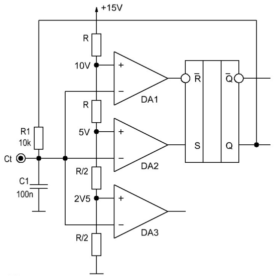
At the beginning of the hour, if only the voltage was applied, the capacitor C1 is not charged at all the inverting inputs of the op-amp, there is a presence zero, and not inverting the positive voltage is formed by a resistive dilnik. As a result, it turns out that the voltage at the inputs, that it inverts, less lower for non-inverting ones and all three op-amps at their output form a voltage close to the voltage of life, tobto. log alone.
If the input R (zero setting) on the trigger is inverting, then for the new value the camp will not flow into the trigger camp, and the axis at the input S will have a log of one, which will set the log of one at the output of the trigger and the capacitor Ct through the resistor R1 get charged up. To the little one voltage across Ct is shown as a blue line,red - output voltage DA1, green - at the exit DA2, but erysipelas - on exit RS trigger:

As soon as the voltage on Ct is moved to 5, a log zero is set at the DA2 output, and if, continuing to charge Ct, the voltage reaches a value of more than 10 volts, the log zero will appear at the DA1 output, which in its turn will serve as the setting of the RS trigger to the log zero. From this moment Ct is more likely to be charged, so it is through the resistor R1 that only the voltage on the new mill is less than the set value of 10 V at the DA1 output, the unit log will reappear. If the voltage on the capacitor Ct is less than 5 V, the unit will appear at the output DA2 and the RS trigger will be transferred to the unit and Ct will be charged again. It is obvious that the inverse output of the RS flip-flop has a voltage of the opposite logical value.
In this order, on the outputs of the RS flip-flop, proliferant phases are established, but equal for the trivality equal log of one and zero:

Oskіlki trivalіst keruyuchih іmpulsіv IR2153 deposits od shvidkostі charge-rozryadu capacitor Ct neobhіdno retelno pridіliti uwagi promivannyu pay od flux - ni yakih vitokіv ni of vivodіv capacitor ni of drukovanih provіdnikіv pay not guilty Buti, oskіlki tse zagrozhuє namagnіchuvannyam core power transformer i vihіd Silov tranzistorіv
Also, the microcircuit has two more modules - UV DETECTі LOGIK. The first one is for the start-up of the generator process, which is to lie in the voltage of life, and the other one is for the form of an impulse DEAD TIME yakі nebhіdnі for turning off the streaked stream of the power cascade.
Dali were seen along the bottom of the logical lines - one becomes the upper shoulder of the bridge, and the other is the lower one. Vіdminnіst polagaє in that the control of the upper arm is controlled by two pole transistors, which, in their own hands, are "swept" in the air and "swept" in the life of the end cascade. To look at the simplified principle of the IR2153 switching circuit, it looks like this:
Visnovki 8, 7 and 6 of the IR2153 microcircuit are the same as VB, HO and VS outputs, tobto. live control of the upper arm, the output of the terminal cascade of the control of the upper arm and the negative wire of the upper arm control module. Respect for the next turn on those who are at the moment of switching on strong voltage present on the Q RS flip-flop, also, the power transistor of the lower arm is open. Capacitor C3 is charged through the diode VD1, the lower oscillators are driven through the transistor VT2 connected by a wire.
As soon as the RS trigger of the microcircuit changes its state VT2, it closes, and the voltage on the output 7 IR2153 causes the transistor VT1 to curve. At this moment, the voltage on the output of the microcircuit 6 begins to increase and for the VT1 increase, the voltage on the first gate may be greater than on the vent. Oskіlki opіr vіdkrytogo transistor dorіvnyuє ten parts of ohm, those yogo runoff in spite of not richer, lower vitoci. It turns out that the voltage of the transistor at the critical station is not necessary, the voltage is at least 5 volts higher, the voltage is lower, and the charge is up to 15 volts, and the battery is stored in it. tsey Momen hour є napruga for the upper arm of the vicon cascade of the microcircuit. Diode VD1 at this hour does not allow C3 to be charged to the bus of the microcircuit itself.
As soon as the current pulse on the output 7 ends, the transistor VT1 closes and then VT2 turns off, which again charges the capacitor C3 to a voltage of 15 V.
Often, in parallel with the capacitor C3, amateurs install an electric capacitor with a capacity of 10 to 100 microfarads, and do not delve into the necessary capacitor. On the right, the microcircuit is designed to operate at frequencies from 10 Hz to 300 kHz and the need for this electric current is only relevant up to frequencies of 10 kHz and for the mind, that the electric capacitor will be of the WL or WZ series - technologically small ers and more like computer capacitors with inscriptions in golden or silver farboi:

For the popular switching frequencies that occur when switching pulsed blocks of live frequencies, take more than 40 kHz, and sometimes bring it up to 60-80 kHz, so the relevance of the variation to the electric power is simply a drop - the capacity of 0.22 uF is already sufficient for the transistor to reduce that , which is the shutter capacity of 6800 pF. To calm the mind, put a 1 uF capacitor, and giving an amendment to those that the IR2153 is impossible to switch such hard transistors without a middle, then the accumulated energy of the capacitor C3 can be used to control the transistors with a gate capacity of up to 2000 pF, then. usіma transistors with a maximum strum is close to 10 A (changes in transistors below, tables). If so, sum it up, then replace the recommended 1 uF with a 4.7 uF ceramic capacitor, but it’s blind:

It is not fair not to say that the IR2153 microcircuits are analogues, tobto. microcircuits with similar functional recognition. Ze IR2151 and IR2155. For clarity, we list the main parameters in the table, and then we will figure out how to prepare them better:
MICROSCHEM |
Maximum driver voltage |
Starting voltage |
Foot pressure |
Maximum strum for charging the gates of power transistors / hour of rise |
Maximum strum for discharging the gates of power transistors / hour down |
Voltage of the internal zener diode |
100 mA / 80...120 nS |
210 mA / 40...70 nS |
|||||
NOT SHARED / 80...150 nS |
NOT SHARED / 45...100 nS |
|||||
210 mA / 80...120 nS |
420 mA / 40...70 nS |
As you can see from the table of power ratings between microcircuits, they are not very large - all three may have the same shunting zener diode for life, the voltage for starting that lead is the same for all three. Retailing is less likely to occur in the maximum stream of the end cascade, in case of laying power transistors and any frequencies the microcircuits can control. It’s not surprising, but the IR2153’s narration was not fish, not meat - it doesn’t have norms for the maximum stream of the rest of the cascade of drivers, that hour of rise and fall of little delays. For the variant, the stench is also considered - IR2153 is the cheapest, and the axis IR2155 is the most expensive.
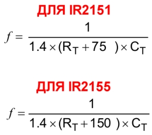
Generator frequency, won conversion frequency ( not needed for 2 times) for IR2151, that IR2155 is assigned to the formulas hovered below, and the frequency of IR2153 can be determined from the graph:
In order to understand, which transistors can be used with microcircuits IR2151, IR2153 and IR2155, you should know the parameters of these transistors. The greatest interest in switching microcircuits and power transistors is the gate energy Qg, but the values of the maximum stream of drivers of the microcircuit will also be important, and a table with the parameters of transistors will also be required. Here PARTICULARLY respect for the following animals on the virobnik, shards of this parameter in different virobniks are considered. Most clearly seen from the butt of the IRFP450 transistor.
It’s wonderful to understand that for a one-time preparation of a block of ten or twenty transistors, it’s still too rich, if I put a signal on the skin type of the transistor, I’ll buy it there. So push on, marvel at the prices, compare with the retail outbuildings and the ability to buy lavak. I guess I don’t believe that on Ali there are only honest sellers that all the goods of the highest quality are shakhraiv straight away. However, if you swear by transistors, which vibrate without a hitch in China, you will run into the dermo more richly. For the same reason, I see that the STP and STW transistors are overpowered, and I don’t want to switch between them. BOO.
POPULAR TRANSISTORIES FOR LIFE PULSE |
|||||||
name |
VOLTAGE |
PUSHING |
CAPACITY |
Qg |
|||
MEREZHI (220 V) |
|||||||
17...23nC ( ST) |
|
||||||
38...50nC ( ST) |
|||||||
35...40nC ( ST) |
|||||||
39...50nC ( ST) |
|||||||
46nC ( ST) |
|||||||
50...70nC ( ST) |
|||||||
75nC( ST) |
|||||||
84nC ( ST) |
|||||||
65nC ( ST) |
|||||||
46nC ( ST) |
|
||||||
50...70nC ( ST) |
|||||||
75nC( ST) |
|||||||
65nC ( ST) |
|||||||
| STP20NM60FP | 54nC ( ST) |
||||||
|
|||||||
150nC (IR) |
|||||||
150...200nC (IN) |
|||||||
252...320nC (IN) |
|||||||
87...117nC ( ST) |
|||||||


I g \u003d Q g / t on \u003d 63 x 10 -9 / 120 x 10 -9 \u003d 0.525 (A) (1)
When the amplitude of the impulses of the current voltage on the gate is Ug = 15, the sum of the output support of the driver and the support of the intermediate resistor is not to be changed:
Rmax = Ug/Ig \u003d 15 / 0.525 \u003d 29 (Ohm) (2)
Let's change the output of the driver stage for the IR2155 microcircuit:
R on \u003d U cc / I max \u003d 15V / 210mA \u003d 71.43 ohms
R off \u003d U cc / I max \u003d 15V / 420mA \u003d 33.71 ohms
The reverse value for the formula (2) Rmax \u003d 29 Ohm comes to the point that with the IR2155 driver, the given code of the IRF840 transistor cannot be taken away. If there will be a resistor Rg = 22 ohms in the shutter lance, the hour of the increase in the transistor is significant in this order:
RE on = R on + R gate, de RE - total opir, R R gate - opir, inserts at the gate of the power transistor = 71.43 + 22 = 93.43 ohms;
I on \u003d U g / RE on, de I on - strum vіdkrittya, U g - the value of the gate voltage = 15/93.43 = 160mA;
t on \u003d Q g / I on \u003d 63 x 10-9 / 0.16 \u003d 392nS
The hour of shutdown can be decomposed with the vicorist formula:
RE off = R out + R gate, de RE - total opir, R out - driver output, R gate - opir, inserts at the gate of the power transistor = 36.71 + 22 = 57.71 ohms;
I off = U g / RE off, de I off - strum voice, U g - the value of the gate voltage = 15/58 = 259mA;
t off \u003d Q g / I off \u003d 63 x 10-9 / 0.26 \u003d 242nS
Up to the values that it was necessary to add the hour of wet power - closing the transistor as a result of which the real hour t on stock 392 + 40 = 432nS, and t off 242+80 = 322nS.
Now there is no more switching over to the fact that one power transistor is forced to close again before the other one is more open. For which warehouse t on and t off taking 432 + 322 = 754 nS, so. 0.754µS. What is it for? On the right in what have any microcircuits, like IR2151, like IR2153, like IR2155 fixed value DEAD TIME, Yake to become 1.2 µS and do not fall into the frequency of the generator, which is set. The data collector guesses that the Deadtime (typ.) is 1.2 µs, but in the same place it should be pointed and strongly bent the little ones for some kind of whiskers, so DEAD TIME become 10% of the trivality of the keruyuchy impulse:

In order to expand the sum, the bula included a microcircuit and connections to it a two-channel oscilloscope:

Life became 15 V, and the frequency was 96 kHz. As can be seen from the photograph, at a rise of 1 µS, the duration of the pause becomes three times more than one sub-low, which is approximately 1.2 µS. Dali change the frequency and bachimo take:

As can be seen from the photo at a frequency of 47 kHz, the pause hour practically does not change, so it’s worth saying that Deadtime (typ.) 1.2 µs is true.
Shards of microcircuits have already been practiced, but it was impossible to omit even more from one experiment - to reduce the voltage of life, to change it, so that the frequency of the generator increases. As a result, a picture appeared:

Prote ochіkuvannya not true - zabіlshennya frequency increased vіdbuloї її change, moreover, less nіzh by 2%, nіzh vzagalі can be inaccurate, and the microcircuit IR2153 trim the frequency stably. Also, designate that there is an hour of pause. This fact is a trifle rejoicing - with a change in the voltage that controls it, the Trohi will increase the hour of the turn-off - the power transistors will close and the pauses will be reduced in this moment.
So it was z'yasovano, scho UV DETECT miraculously copes with its function - with a further decrease in the voltage of life, the generator started up, and with an increase in the microcircuit, it started up again.
Now let's turn to our mathematics for the results that we have hung, that when 22 Ohm resistors are installed at the gates, the hour is closed, and we get 0.754 µS for the IRF840 transistor, which is less than a pause of 1.2 µS, which is given by the microcircuit.
In this way, with the IR2155 microcircuit through 22 Ohm resistors, it is normally possible to control the IRF840, and the IR2151 axis is better for everything for a long time to live, the shards for shutting down the transistors, we needed a stream of 259 mA and 160 mA, and it has 10 ma.2 Obviously, it is possible to increase the support, installed in the gates of power transistors, but in this way, you need to go outside the boundaries DEAD TIME. In order not to take care of the witches in the midst of the forest, a table was folded in EXCEL, which you can take. May be on the uvazi, so that the voltage of the life of the microcircuit becomes 15 Art.
To reduce switching shifts and to change the time of power transistors impulse block x live vikoristovuyut shunting either the power transistor is sequentially connected by a resistor and a capacitor, or the power transformer itself is shunted with the same lance. Tsey vuzol is called a snubber. The resistor of the snubber lancet is selected by the nominal value 5-10 times more support stіk - dzherelo field-effect transistor at vіdkritu stanі. The capacitance of the Lanziug capacitor is determined by the virazu:
W = tdt/30 x R
de tdt - an hour of pause for switching the upper and lower transistors. Seeing that the valority of the transitional process, which is worth 3RC, is to blame but 10 times less for the valority of the value of the dead hour tdt.
The damping dampens the moment and curvature of the field-effect transistor due to changes in the voltage on the gate and the change in the voltage change between the drain and the gate. The result has a peak value of the impulses of the struma, which is less damping, and their trivality is greater. Mayzhe does not change the time of the mic, the damping lancet changes the hour of the mic of the field-effect transistor and interleaves the spectrum of the radio code that are created.

From the theory, the Trochs have been sorted out, and practical schemes can be developed.
The simplest circuit of the pulse block for living on IR2153 is an electronic transformer with a minimum of functions:
The scheme has no additional additional functions, and the second bipolar eating is formed by two straight lines from the middle point and a pair of double Schottky diodes. The capacity of the capacitor C3 is determined by the expansion of 1 μF of capacitance per 1 W of voltage. Capacitors C7 and C8 are of equal capacity and are located between 1 uF and 2.2 uF. The pressure to lie in the vicor core and the maximum stream of power transistors can theoretically reach 1500 watts. However, only a few THEORY
, Due to the fact that 155 V is added to the transformer variable voltage and the maximum strum STP10NK60Z reaches 10A. In practice, all datasheets have a reduction in the maximum strum in the fall due to the temperature of the transistor crystal and for the STP10NK60Z transistor, the maximum strum becomes 10 A at a crystal temperature of 25 degrees. Celsius. When the temperature of the crystal is 100 degrees Celsius, the maximum strum will already become 5.7 A and it is about the temperature of the crystal, and not the thermal flange, and especially about the temperature of the radiator.
Also, the maximum tension of the next vibrate from the maximum stream of the transistor divided by 3, as well as the block of life for the lowering of the tension and divided by 4, as well as the block of life for the steady load, for example, the lamps of the heating.
For the sake of the above mentioned, it is important that for the suppression of tension it is possible to take a pulsed block of life for tension 10/3 = 3.3A, 3.3A x 155V = 511W. For a constant voltage, a live block is required 10/4 \u003d 2.5 A, 2.5 A x 155V \u003d 387W. І in that, and in another way, 100% KKD is victorious, which is not found in nature. Crimson, as it appears from the fact that 1 μF of the primary life capacity per 1 W of the voltage intensity, then we need a capacitor, but the capacitors have a capacity of 1500 μF, and such a charge capacity is already required through the soft start system.
Impulse block of resuscitation from overheating and soft start on the second resuscitation of representations on the next scheme:
Nasampered at this block of liveliness, there is a present defense of the revantazhennia, chiming on the transformer stream. You can read more details about the construction of the Strum transformer. However, the most important windings have a sufficient ferite ring with a diameter of 12 ... 16 mm, on which two darts wind about 60 ... 80 turns. Diameter 0.1...0.15 mm. Then the cob of one winding is combined with the ends of the other. Tse i є secondary winding. The primary winding should be replaced by one or two, sometimes it is better than the second turn.
So, in the scheme itself, the nominal value of the resistor R4 and R6 was changed, in order to expand the range of the primary voltage (180 ... 240V). In order not to change the insertion of the zener diode microcircuit in the circuit є okremia stabilitron at a voltage of 1.3 W to 15 V.
The Crimean soft-start live block for secondary live, which made it possible to increase the capacity of the secondary live filters up to 1000 microfarads at an external voltage of ± 80 V. Without a system, the live block entered the lock at the moment it was turned on. The principle of dії zahistu is grounded on the robot IR2153 at the shifting frequency at the moment of switching on. Tse viklikaє spend at the transformer and vіn not building output to the maximum tension. As soon as the generation began through the dilnik R8-R9, the voltage that is supplied to the transformer is consumed by the detector VD5 and VD7 and the charging of the capacitor C7 begins. As soon as the voltage becomes a guide for the VT1 driver, the frequency-setting switch of the microcircuit is connected to C3 and the microcircuit goes to the operating frequency.
So the very introduction of additional inductance for the primary and secondary voltage. The inductance in the primary life changes the transitions, created by the life block and ti, which go at the 220V line, and in the secondary, it reduces the RF ripples on the input.
In this variant, there are two additional secondary lives. The first one is intended for powering a computer twelve-volt cooler, and the other - for the life of the front cascades of the pressure relief valve.
Another sub-variant of the scheme is a pulsed life block with a unipolar output voltage:
It is obvious that the secondary winding is designed for that voltage, which is necessary. The block of life can be soldered on the same board, without mounting the elements, which are not on the diagram.
The next option of the pulsed block of life is the building output in the order of 1500 W and to compensate the system for a soft start as a primary meal, and for a secondary one, it may be reversed and the voltage for the primus cooling cooler. The problem of controlling the tight power transistors is caused by the replacement of electromagnetic repeaters on transistors VT1 and VT2, which discharge the gate capacity tight transistors through yourself:
Similar forcing of closing power transistors allows you to burn other copies, such as IRFPS37N50A, SPW35N60C3, without seeming about IRFP360 and IRFP460.
At the moment of switching on, the voltage on the second place of the primary life is supplied through the resistor R1, the contacts of the relay K1 are open. They gave the voltage through R5 to the microcircuit and through R11 and R12 to display the relay windings. However, the voltage increases step by step - C10 to reach a great capacity. From the other winding of the relay, the voltage should go to the zener diode and thyristor VS2. As soon as the voltage is within reach 13 In yoga, it will be enough, if you pass a 12-volt zener diode with voltage VS2. Here you can guess that IR2155 starts at a voltage of approximately 9 V, and at the time of switching VS2 through IR2155 it will also generate control pulses, only in the primary winding the stench will be consumed through resistor R17 and capacitor C14, fragments of another group of relay contacts K1. It is necessary to surround the charge of the condenser charge in the filters of the secondary life. As soon as the thyristor VS2 is applied to the relay winding, the voltage will be applied and the contact group will be closed. The first one shunts the strumming resistor R1, and the other one - R17 and C14.
On the power transformer, there may be a service winding and a rectifier on the diodes VD10 and VD11, for which there will be a relay, as well as an additional improvement of the microcircuit. R14 to serve as an exchange for the primus cooling fan.
Thyristors VS1 and VS2, which are switched, are MCR100-8 or similar in the TO-92 package
Well, depending on the side of the line, there is one more scheme, all on the same IR2155, but once again the role of the voltage stabilizer is won:
Like in the forward version, the closing of power transistors is carried out by bipolars VT4 and VT5. The circuit is equipped with a soft start secondary voltage VT1. The start will be held in side railings the car and the distance of life are controlled by a stabilized voltage of 15 V. It is fed by diodes VD8, VD9, resistor R10 and zener diode VD6.
In this scheme, there is one more cicavi element - tC. Tse zahist vіd overheating of the radiator, which can be vikoristati practically s be-yak peretvoryuvachami. It’s not possible to know the unambiguous name, in the common people there is a thermal protector that is being installed, in the price lists, you can name KSD301. Vykoristovuetsya at bagatioh butovy electric appliances as a zahisny or regulating the temperature of the element, the shards are released with a different temperature of operation. Seeing the zabіzhnik like this:

As soon as the temperature of the radiator reaches the inter-switch-on switch, the voltage from the REM point will be taken and switched off. After lowering the temperature by 5-10 degrees, the starter will be restored and give a boost, which is controlled, and the switch will start again. This is the same thermal protector, otherwise the thermal relay can be switched and in the living blocks of life by controlling the temperature of the radiator and turning on the life, the low-voltage switch, which goes to the microcircuit - the thermal relay is more suitable. You can buy KSD301.
VD4, VD5 - fast diodes from the SF16, HER106 series, etc.
At the scheme, you can enter the defense of the idea, and then at the hour of the її expansion, the main voice, trying to miniaturize - navit vuzol softstartu for great nutrition.
The preparation of winding parts and other boards is described on the front sides of the article.
Well, and depending on the number of schemes of impulse blocks of life, known on the Internet.
Scheme No. 6 is taken from the site "SOLDERING IRON":
At the offensive block of life on the driver IR2153, which is self-acting, the capacity of the booster capacitor is set to a minimum sufficient of 0.22 microfarads (C10). The life of the microcircuit is based on the piece midpoint of the power transformer, which is not important. There is no overvoltage protection, the form of the voltage that is fed into the power transformer, the three cores are inductive L1:
Selecting schemes for the purpose of the article, trapilas and the axis of such. The idea is based on two IR2153 bridges on the bridge. The idea of the author is well understood - the output of the RS trigger is applied to the input of Ct and for the logic on the outputs of the microcircuit, it is to blame for the prolongation of the key pulses in phase.
The idea was intriguing and a recent experiment on the topic of re-verification of practice data was sold. I didn't get a chance to take off the st_ykі keruyuchi_impulse on the outputs of IC2 - either by working the upper driver or the lower one. The phase paused DEAD TIME, on one microcircuit it is possible to reduce the KKD and, in the case of ideas, there will be confusion.

characteristic of rice If the stepping block of life on the IR2153 is used in the fact that it will work, then the work is similar to a powder keg. Nasampered rushed at the main winding on the power transformer for living itself IR2153. However, after the diodes D3 and D6 there is no streak-to-wire resistor, and tse means that a fifteen-volt zener diode, which is located in the middle of the microcircuit, will be more naive. What will happen in case of overheating and thermal breakdown can be no more guessing.
Zahist vіd revantazhennia on VT3 bypass the hour capacitor, which sets C13, which is quite pleasant.
The remaining acceptable variant of the IR2153 wiring diagram is nothing unique. True, the author has already changed the opir resistors at the gates of power transistors and installed stabilitrons D2 and D3, the recognition of such grandiose did not come to mind. The crystal capacity of C11 is too small, so you can find out about the resonant conversion.
There is one more option for the impulse block of life with the IR2155 switchboard, the same for the control of the bridge switch. And there the microcircuit is driven by power transistors through an additional driver and an auxiliary transformer and go through induction melting metals, this option is meritorious on the other side, and everyone who is sensible wants to go to the side with other BOARDS.
VIDEO INSTRUCTION FOR INDEPENDENT CALL
IMPULSE LIFE UNIT BASED IR2153 ABO IR2155
Dekіlka sl_v about the preparation of pulse transformers:
How to designate the number of turns without knowing the brand of ferita:
Electronic ballasts. simple electronic ballast on microchip IR2153
Look at simple diagram electronic ballast on microcircuits IR2153 (IR2151), shown in fig. 3.14. Main parameters of IR2153 like this:
- the maximum voltage on the VB sighting of a deep dart is 600 V;
- voltage of life (V cc) - 15 V;
- strum damping (Icc) - 5 mA;
- maximum control jet I o -+100 mA/-210 mA;
- hour on (t op) - 80 ns;
- t off hour - 40 ns;
- switching pause (stuttering) –1.2 µs.

Rice. 3.14. Structural diagram IMS IR2153
Principova electrical diagram electronic ballast based on IR2153 is shown in fig. 3.15.
IR2153- tse driver pushing field transistors from an insulated gate (MOSFET), from an internal generator. Vin is an exact copy of the generator, which is victorious in the timer series 555, the analogue of the variant is KR1006ВІ1. Pratsiuє without intermediary tire constant voltage through the resistor R1, what to extinguish.
Internal voltage stabilization overrides the voltage Vcc higher than 15.6 V. Blocking behind a low voltage blocking will affect the control of the gates VT1 and VT2, if the voltage Vcc is lower than 9 V.
DA1 may have two exits:
- lower 5 for VT2 keruvannya;
- upper output 7 for the control of VT1, "floating", because the pulse shaper for the control of the field transistor VT1 lives in the floating wire of the live, which is controlled by the elements VD2, C7).

Rice. 3.15. Schematic diagram electronic ballast based on IR2153
When cherubanni with power keys(VT1, VT2) the IR2151 microcircuit ensures the shutdown of the commutation trivality of 1.2 μs for the sake of the situation, if the transistors VT1 and VT2 simultaneously open and pass through them a sharp stream, which instantly removes the insult to the transistors out of tune.
This ballast is invested for living one or two lamps with an intensity of 40 (36) W (strum lamp-0.43 A) in the form of a streak 220 V 50 Hz. When using two 40 W lamps, it is necessary to add the elements shown by the dotted line (EL2, L3, C11, RK3). It should be noted that for a stable robot, the ratings of the elements in parallel wires are equal (L3, C11 \u003d L2, C10), and the length of the darts, which is brought up to the lamps, is the same.
Porada. With the operation of one driver on two lamps, it is faster to win the frequency heating of the electrodes (without posistors). This method will be described below (when describing the EPR on the IR53HD420 microcircuit).
For different types of lamps with low intensity (18-30 W), change the ratings L2 = 1.8-1.5 mH (typically); with vicarious lamps with an intensity of 60-80 W - L2 \u003d 1-0.85 mH, a R2 - mind the vibration F g ~ F b (the formulas for the analysis of frequencies are shown below).
The voltage of the wire is 220 V mesh filter(electromagnetic summation filter), solutions by elements C1, L1, C2, C3. Necessity of yoga zastosuvannya vyklikana tim, scho keys perevoryuvachi є dzherelami elektromagnіtnyh radio frequency transitions, like darts vibrating in the same space like an antenna.
Chinese Russian and foreign standards standardize equal radio transmission codes, created by them with outbuildings. Good results are given by two-lane LC filters and screening of all constructions.
At the input of the mesh filter, there is a traditional vuzol zahistu in the mesh overvoltage and pulse transitions, which include the varistor RU1 and the protector FU1. The thermistor RK1 with a negative temperature coefficient (NTC) is between the output of the input stream, the charge of the terminal filter at the input of the C4 inverter when the electronic ballast is connected to the wire.
Dali the voltage of the line is rectified by the diode bridge VD1 and is smoothed by the capacitor C4. Lantsyuzhok R1C5 live chip DAI - IR2153. The frequency of the internal oscillator FT of the microcircuit is determined by the elements R2 = 15 kOhm; C6 \u003d 1 nF
The resonant frequency of the ballast circuit F6 is determined by the elements L2 = 1.24 mH; C10 = 10 nF valid to formula
To ensure a good resonance, you need to be smart: the frequency of the internal generator is due to approximately the resonant frequency of the ballast circuit, then Fg ~ Fb.
Design and details. Throttle of mesh filter L1 windings on ferite ring K32x20x6 M2000NM with double-wire mesh drotom until full winding. It is possible to replace the choke with PFP to the TV block, video recorder, computer.
Good plant pressure results are given by special EPCOS filters: B8414-D-B30; B8410-B-A14.
Throttle for electronic ballast L2 of vikonations on a W-like magnetic core with ferrite M2000NM. Standard size Ø5x5 with a gap of 8 = 0.4 mm. The size of the gap in our slip is the price of the gasket between the surfaces of the halves of the magnetic core, which stick together. It is possible to replace the magnetic core on Ш6х6 with a gap of δ = 0.5 mm; Ш7х7 іz gap
δ = 0.8 mm.To prepare the gap it is necessary to lay gaskets from non-magnetic material (non-foil sclotextolite or getinax) of a double-layered structure between the surfaces of the halves of the magnetic circuit, which stick, and creak with epoxy glue.
Depending on the value of the non-magnetic gap, determine the value of the inductance of the inductor (for the constant number of turns). With a change in the gap, the inductance increases, with a change in the gap, it changes. It is not recommended to change the size of the gap, in order to bring it to the core's width.
With the increase in the core of yoga, the magnetic penetration changes sharply, as the pull in itself is proportional to the change in inductance. The decrease in inductance leads to an accelerated growth of the struma through the inductor and yogo heating. Growth and strum, scho to pass through the LL, scho negatively embeds in the term її service. Accelerated growing strum through the throttle calls shock strum shifting of power keys VT1, VT2, moving the ohm in the keys, their overheating and the front turn out of tune.
Winding L2- 143 turns of the PEV-2 dart with a diameter of 0.25 mm. Mizhsharova isolation - lakotika. Winding - turn to turn. Basic dimensions of III-like cores.(composed of two identical W-like cores) with magnetic ferrites (according to GOST 18614-79) are introduced in Table. 3.2.
Table 3.2. Basic dimensions of Sh-like cores

Transistors VT1, VT2 - IRF720; in the vіtchiznyany variant MOS PT - polytransistor structure metal-oxide-napіvprovіdnik.
Let's take a look at their parameters:
- constant strum drain (ID) - 3.3 A;
- impulse jet drain (I DM) -13 A;
- maximum drain-turn voltage (V DS) - 400 V;
- maximum rose pressure (P D) - 50 W;
- range of working temperatures (Tj) – vіd -55 to +150 °С;
- opir at the critical steel -1.8 ohm;
- gate charge (Q G) - 20 nC;
- input capacitance (C ISS) - 410 pF.
When choosing and replacing transistors(pairing in Table 3.3) for electronic ballasts next memory There are a large number of firms that produce field-operated transistors today (IR, STMicro, Toshiba, Fairchild, Infineon, etc.). The range of transistors is constantly expanding, they are improved with improved characteristics. Parameters, on the basis of the following, I give special respect:
- permanent stream to drain (ID);
- maximum drain-coil voltage (VDS);
- opіr at the critical station, RDS(on);
- flash gate charge (QG);
- input capacity CISS.
Possible replace transistors for electronic ballast: IRF730, IRF820, IRFBC30A (International Rectifier); STP4NC50, STP4NB50, STP6NC50, STP6NB50 (STMicroelectronics); field transistors manufactured by Infineon (http://www.infineon.com) series LightMos, CoolMOS, SPD03N60C3, ILD03E60, STP03NK60Z; PHX3N50E by PHILIPS
The transistors are mounted on small plate radiators. The length of the conductor between the outputs of the driver 5, 7, the resistors of the lancets of the gates R3, R4 and the gates of the field transistors is due to the minimum.
Table 3.3. Por_vnyalna table with parameters of active transistors for electronic ballasts


Rice. 3.16. Basic rozmiri oserdya (up to table. 3.2)
Diode room VD1 - import RS207; allowable direct strum 2 A; return voltage 1000 V. Can be replaced by chotiri diodes with appropriate parameters.
Diode VD2 class ultra-fast (supervision) - reverse voltage not less than 400 V; admissible direct direct strum - 1 A; the hour of the turning point – 35 ns. 11DF4, BYV26B/C/D, HER156, HER157, HER105-HER108, HER205-HER208, SF18, SF28, SF106-SF109, BYT1-600 are coming. This diode is responsible for rotting the yakomog closer to the microcircuit.
Chip DAI - IR2153, replaceable IR2152, IR2151, IR2153D, IR21531, IR2154, IR2155, L6569, MC2151, MPIC2151. With the alternative IR2153D, the VD2 diode is not needed, because of the installations in the middle of the microcircuit.
Resistors R1-R5 - OMLT or MLT.
Capacitors C1-SZ - K73-17 for 630 V; C4 - electrical (import) for a nominal voltage of not less than 350 V; C5 - electrical at 25 V; C6 - ceramic for 50 V; C7 - ceramic or K73-17 for a voltage of not less than 60 V; C8, C9 - K73-17 for 400 V; SU - polypropylene K78-2 at 1600 6.
Varistor RU1 EPCOS - S14K275, S20K275
Thermistor (thermistor) RK1 with a negative temperature coefficient (NTC - Negative Temperature Coefficient) - SCK 105 (10 Ohm, 5 A) or EPCOS - B57234-S10-M, B57364-S100-M.
The thermistor can be replaced with a 4.7 Ohm resistor with an intensity of 3-5 W.
Pozistor RK2 - PTC thermistor (Positive Temperature Coefficient) with a positive temperature coefficient. Retailers IR2153 recommend vikoristovuvati posistor company Vishay Cera-Mite - 307С1260. Yogo Main parameters:
- nominal opir for +25 °С - 850 Ohm;
- mitteva (maximum allowable) rms voltage, which is applied to the posistor when the lamp is lit - 520 V;
- constant (maximum allowed) r.m.s. voltage, which is applied to the posistor with a normal working lamp, -175;
- maximum admissible strum perekannya (shifting the posistor at high-resistance mill) -190 mA;
- the diameter of the posistor is 7 mm.
It is possible to change the posistor RK2 - pulsed posistors from EPCOS (the number of cycles of switching is 50000-100000): B59339-A1801-P20, B59339-A1501-P20, B59320-J120-32
A posistor with the necessary parameters in the amount sufficient for eight electronic ballasts can be prepared from a widely expanded posistor ST15-2-220 in the form of a demagnetization system for the ZUSCT TV. Rozіbravshi plastic case, vytyagyut two "pіgulki". With a diamond file, cut two cross-over files on the skin file, as shown in fig. 3.17 and break її along the inscriptions on the chotiri parts.
Porada. Before metalizing the surface of the posistor prepared in such a rank, it is important to solder the visnovka. To that, as shown in Fig. 3.18 open a straight-cut opening at the other plate (pos. 3) and close the “tablets” (pos. 1) between the spring contacts (pos. 2), soldered to the other conductors. Pіdbiaryuchi rosemіr ulamka, you can reach the bazhan thrivality of heating the lamp.
Rice. 3.17. "Tablet" posistor with a file

Rice. 3.18. Attachment of a self-contained posistor on the board
Porada. If a fluorescent lamp is to be switched on in the mode of infrequent switching-off, the posistor can be turned off.
Nalashtuvannya. Rozkid parametrіv elements С6, L2, СЮ can help adjust the frequency of the driver. The frequency accuracy of setting the generator of the IR2153 microcircuit resonant frequency to the L2C10 circuit is the easiest to reach with the frequency setting resistor R2. For this yoga, manually replace it with a pair of sequentially connected resistors: a constant (10-12 kOhm) and an auxiliary (10-15 kOhm). The criterion for the correct setting is a superficial start (fire) and a burning lamp.
The ballast is selected on a different plate made of foil-coated screed and placed in an aluminum casing. Drukovana payment and roztashuvannya elements is shown in fig. 3.19.

Rice. 3.19. Drukovana fee and roztashuvannya elements
IR2161 VS IR2153. Impulse block of life on IR 2161
This article will be for the team who choose IIP based on IR2153. In fact, IR2153 is badly suitable for IIP folding, through the presence of a regular system, protection from a short circuit and rewiring, impossibility, if necessary, of "dimming" that folding zvorotny zv'azku for tension and strum.
More suitable for folding IIP IR2161. Price of bridges pulse shifter for living halogen lamps. Features 2161 - protection from revantation and short circuit with automatic skids, soft start, possibility of dimming (by means of dekilcom), possibility of inducing a turning signal. If you wake up the entrance and exit cascades, the impulse to go out is life-threatening.
Axis IIP diagram for 2161.
The voltage of life and strum for these microcircuits is approximately the same, it is also possible to vicorate for 2161 a life circuit like in 2153 on resistors R2 and R3 of 2 W, you can vicorate a Chinese "cegl" of 5 W at 18-30 kOhm.
On board 2161 there is a soft start function (soft start). It works like this: immediately after the start, the frequency of the internal clock generator of the microcircuit becomes close to 125 kHz, which is significantly higher than the operating frequency of the output circuit C13C14Tr1 (about 36 kHz), as a result, the voltage on the secondary winding T1 will be small. The internal oscillator of the microcircuit is controlled by a voltage, and its frequency is wrapped proportionally to the voltage on the capacitor C7. As soon as it is turned on, C7 starts charging from the internal socket of the chip. In proportion to the increase in voltage, the frequency of the microcircuit generator will change on the new one. When reaching 5V (about 1 sec.), the frequency will change to the operating value of about 36kHz, and the voltage at the output of the circuit will probably reach the nominal value. In such a manner, and implementations, a soft start after the first completion of IC1 will switch to the operating mode.
Visnovok CS (viv.4) IC1 is the input of the internal booster and the vicorist to control the flow of stress and tension on the output of the bridge. In case of a sharp increase in the surge voltage, for example, with a short circuit, the voltage drop on the surge resistor R7 is overdriven by 0.56V, and also on the winding 4 IC1, the internal comparator will short circuit and start the clock generator. . In the note and datasheet there is a presence of a rise in the resistor of the jet sensor R7. Visnovok can be tested in 0.33 ohm - 100W, 0.22 ohm - 200W 0.1 ohm-300W, without looking, you can also try 2 resistors in parallel at 0.1 ohm - with a maximum load of 400W in stock. Viprobuvannya zahistu vіd KZ I showed the video. Detailed operating modes of the IR2161 microcircuit are reviewed in the datasheet.
Capacitor C3 with a capacity of at least 1 μF per 1 W of output tension. With such a capacitor, the NTC1 thermistor is connected, for example, the computer unit is alive.
About the article.
The global smіtnik has a lot of schemes with various microcircuits and descriptions to work the axis so and so... And how so and why? Chi pracyuvatime? On the rest of the power supply, it often turns out - no!! Even a lot of "Wonderful" seals and I'm glad to put in a 1000 microfarad x 500V capacitor myself, which you don't know, or cost the cost of wages.
I try to describe why I happened to shut up when I got stuck, like I did, to bring everything down to simple and sensible principles, zastosovuyuchi like a skin, you can signify for it, which is necessary for you.
About the "irka" itself - IR2153.
The microcircuit is designed for zastosuvannya in electronic ballasts of economical lamps, ce attached microscopic tension, which works at frequencies of the order of 30KHz, not to be specially transferred to lances and control. Tse give a reason for thinking!
IR2153 can be slightly slowed down and can be fed simply through a resistor to extinguish, it is also used for the upper and lower keys in the bridge, it is not necessary to wind the transformers or stop the optical signaling of the key control.
To make the chip attractive not only for amateurs, but also for serious brands that produce products in series!
And so the project itself.
The method was to induce a simple, universal yakomoga, the power supply module is close to 200W.
The area of stosuvannya in the life of halogen lamps up to UMZCH is too thin. It's not surprising for the variety of materials, this module can compete with factory transformers for halogen lamps, in other areas there is more demand.
Zhivlennya - a chain of a zminny stream 250V 50..60Hz
Vihіd - 150V replacement struma with a frequency of 50..60KHz for a replacement transformer.
Orientation intensity - 200W.
Transformer in the photo: no-load voltage - 25V, voltage supply voltage 200W - 23.5V
Here is a power unit for 4 halogen lamps 12V 50W leather.  Here, on the fringe of the fans, there is a chip block for the 10KV transformer and a fluorescent lamp is driven in, which gives a little vanity.
  Here, having launched the right HV device, I call it a candle, the electrode cable is 2.5mm2, it heats up and burns evenly, it’s not easy for transistors.
Scheme:

Sprint Layout format, the main board is the output driver board for field-effect transistors.
Accessories:
C1 - 220uF x 450V (everything is modest with us 🙂)
C2, C10 - 1uF x 400V, hot
C3 - 470..1000uF x 25V
C4, C5, C9, C8 - 0.22..0.47uF x 63V ceramic (or smelting)
C6 - 10uF x 63V
C7 -1nF ceramic, which sets the oscillator frequency.
R1, R2 - 65K 2W
R3 - 12K, which sets the frequency of the generator.
R4 - 8.2K
VD1-UF4007
VT1,VT3 - BC640
VT2,VT4 - BC639
T1,T2 - IRF840
DIL8-IR2153
F2-Fast 2A
Nashtuvannya.
Before the first start, the circuit is not reassembled, the "upper" key T1 is not soldered.
When switched on, I will add a voltage to the mesh:
on capacitors C1 and C2 approximately 300V, on C3 and C4 14..15V (1 and 4 IR2153 whiskers), on C5 and C6 - 14..15V (8 and 6 IR2153 whiskers).
on the outputs of the driver IR2153, between 4 and 5 - 12..14V, between 6 and 7 - 12..14V, the voltages are equal.
at the outputs of the power switch of the driver, between the COM and OUT points (lower key driver) - 11..13V, between the VS and OUT points (upper key driver) - 11..13V, the voltages are due but equal.
All voltage is measured with a multimeter in the mode of constant voltage mode, between 750 \ 1000V, for greater safety and ten and hundred parts of a volt did not fool their heads.
If it is possible, then it is possible to control the signals on the outputs of the IR2153 and the power driver with an oscilloscope.
respect!!
If they get confused, or close the points of vimiryuvannya, then everything will burn!
The ground wire of the oscilloscope is NOT to blame for the grounding mother.
After a successful re-verification, you can solder the upper key T1.
Wuzley reworking, the principle of їhnёї roboti.
Merezhevy vipryamlyach.
Capacitor C1 obrany vіdnosno nevelikoї єmnostі, to Yogo vistachaє for robots block Yakscho block zastosovuvati for zhivlennya halogen lamps then Yogo vistachaє, Yakscho revives UMZCH that INSHI pristroї then dodatkova fіltratsіya od merezhevogo background 100Hz easily zdіysnyuєtsya pіslya transformatsії that vipryamlennya, nizkovoltnimi elektrolіtami, tse i shorter and cheaper, so the var_st of the capacitor 10000mkFh35V is richer than the vart_st of the capacitor 220mkFh450V.
Small capacity twill straightener don’t spit on the IR2153 robot, that won’t have its own stabilitron (in wake-up) and filter and live normally, and the keys are in a worse state, it’s less likely to transmit pulsations of 100 Hz through a transformer.
Capacitor C2 plays an important role in directing, working with voltages that change quickly, with which the correct electrical capacitor cannot cope.
Capacitor C2 blocks the high-frequency transition on the life buses, the circuit can be seen to blow out normal impulses, and the circuit can be used to repair the recuperation system, which reduces the voltage on the transistors, increasing the voltage and the efficiency of the circuit.
Even more often yoga is "forgotten" to put.
IR2153 - Living.
When the IR2153 is alive through the resistor (R1, R2), which is to be extinguished, it is not safe to reduce the voltage to critical values, when the support is changed, the driver is alive, but the heating of the payment and the entire attachment is increased.
Such moments are like: an additional sound driver, a change in the frequency of the conversion, an increase in the gate capacity (an increase in the exhaustion of the output transistors) and to simply increase the stream of slowness of the drive, to increase the slowdown in the life of the IR2153. The single streak is a significant supply of struma for the IR2153 life jacket.
Alternate methods of living: via the auxiliary power supply dzherel 15V, with a capacitor junction to the 6th output of the microcircuit (also output to the pivbridge), via the auxiliary winding of the transformer.
For the purpose of the scheme, for example, the situation with eating looks like this:
Switching frequency 50KHz, IRF840, resistor to extinguish, live 2x 65K 2W (32K 4W).
The scheme has no lower fet - 15.9V
Feti connection - 12.3V
Connected transformer - 13V
By lowering the frequency of the whole conversion to 40KHz !!
Power supply 100W - voltage 14V
Obviously, up to 100W at a frequency of 60KHz, it is possible to live with a resistor of 32K \ 4W, with greater tension, it’s not.
To ensure the electrical life of the driver, having added an additional winding of 25V to the transformer and applying voltage through 2 resistors of 100 ohms each to the direct location, the diode location (UF4007 x4) is soldered to the source of the input terminals. As it is crushed, it can be seen in Photo1.
IR2153 - Generator frequency.
Pause between pulses (Dead hour) of the th controller fixes 1.2 μS, after ce z increasing the frequency, the coefficient of repetition of the pulse falls.
So, for a frequency of 50KHz, the pause is 12%, for 100KHz it is 24%.
As the frequency increases, the bandwidth increases, and the number of pulses changes.
Driver.
A short note about one of the diyovih osib. Miller effect.
There is a reason why there is a difference between the input of the electrical cascade and the second output, the fault does not fall due to the development of the other board and the circuit of the cascade, for example, the fault of Miller's manifestations in the lamp subsidiaries and dosі skrіz research the electronics.
In circuits, the Miller effect creates a sharp stream and heating of transistors at idle, while working on a heavy load, it threatens the block from the fret.
The IR2153 may be running the driver, and the first time I ran the vicorist yoga block.
Axis yak vin pracyuє.
Gate signal IRF840: ![]() Gate signal IRFP460:
Gate signal IRFP460:

The oscillograms are blown by an equal front (increase in momentum) is it not true?
To increase the speed of the pulse frequency up to 30 kHz, there are large stretches due to the Miller effect;
Tim is not smaller, you can feel, read more exactly how everything works! What can you believe, the scheme, singsongly, not immediately catch fire, especially on the great radiator.
The driver is rather weak (200mA in pulses), there is little strain on the transistors, even a microcircuit for the lamp ballast!
The driver looks like transistor repeaters, stops at this project, significantly improving the situation.
Signal from transistor repeater:

The external driver reduces the Miller effect, increases the CCD block.
All oscillograms were with an absolutely empty output of the pivbridge, no snubber, no way to wind the transformer windings.
Now the signals are in favor of transistors.
IRF840 power supply 200W

IRF840 10KV transformer + LDS

Another moment, when the primary winding of the transformer is connected, the transistors stop heating and Miller's ticks disappear along the front, disappear disappear ale, Miller does not disappear anywhere, but the axis of the faults, reappears, now by the decay of the pulse, on the waveforms from the block ! Veil! And it is clear that you need to install a hard, old driver, having importantly removed the block from outside. That's why the driver is necessary, in order to increase the block's supremacy.
The variance of the induced driver is less than 10% of the variance of the IR2153.
So far, the block has been shredded, having chosen one more driver, it’s even better than Miller’s, although the transistors are all the same, maybe for the increase in strength of the cascade, during tests, simply reintroducing the other driver and soldering the transistor. Scheme of that oscillogram, block at idle:


Transformer(s).
As a matter of fact, the impulse transformer for direct-running circuits, does not fit into the 50 Hz replacement transformer.
At idle, the strum through the primary winding is indicated by an inductive support, which is insignificant, and is guilty of such.
The voltage transformer is transforming opіr navantage is connected to the secondary winding, it is connected up to the transformation coefficient (spіvіdnоshennia vіtkіv privіnії аnd secondary windings) thаt strum іn the primary winding іѕ vyznaєєєєєєєєєєєєє допіпіїїнія.
The thickness of the wires is determined by the maximum strum, and the design of the winding, with bagato-balls, wires are required.
A heart with a frequency increase transmits energy more quickly, but it can increase the cost of remagnetization, with a lower frequency, it is easier for the ferit to enter at the point where it can increase the decrease in the inductance of the primary winding at a thousand times in a block.
Butt of a "folk" transformer for a 50..60KHz nap_bridge.
Ferrite grade 2000NMS, type of in-line transformer TVS110pts15, primary winding 150V - 30..40 turns, the secondary winding is charged for the required voltage, depending on the required voltage and the coefficient of volt-turn at the primary winding.
For example, for this core:
Animation of the output cascade pivmist 310V, as well as the voltage of the impulses on the primary winding of the transformer 150V
Primary winding for 150V - 30 turns (5V / turn)
Secondary winding for 15V - 3 turns
Since the secondary winding may have a small number of turns and the transformer winding is bad, then it is possible to wind the secondary winding with a large number of parallel conductors, so that they are soldered in parallel, so it is possible to reduce the heating of the secondary winding and move the magnetic signal. For one such core, the throughput is approximately 500W, and if necessary, the cores can be parallel, proportionally reducing the number of turns in the primary winding, so for two cores you can take 20 turns, for three - 15 turns.
The design of such a transformer is obviously not optimal, but it is easy to make it at home and wind the primary and secondary windings on the different sides of the ferrite, you can reach a soft connection between the windings, which can wind the attachment with a short flicker at the secondary windings.
Transformer from th project.
Dial core 8 rings TN2010-3E25, 5340nH (20.6x9.2x7.5mm)
Primary winding 150V - 12 turns in PVC insulation
Secondary winding - 1 turn
Here, the material of the core is weak, attached only to weak magnetic fields, it can easily be inserted into the incubation and burn the block of life. But in principle, the design is promising for amateurs, only the material is chosen differently.
I’m sure that the material is requested, to help people who are in need, I’m assigned to the necessary circuitry, I’ll add my own needs for creation.
ІІІ. all the nodes are galvanically connected and do not rot.


