Impulse dzherel zhivlennya 10884, and the principle of the scheme. Structural diagrams of impulse cells for living
Zrobiv shchey іvertor, schob could live in vіd 12, so avtomobilny variant. After that, having grown everything at the plan of the ULF, food was delivered: what is now yoga? Navit for quiet tests themselves, or just listen? Thinking about all the ATX BP, but when you try to “heap”, the BP is going to zahist, but you don’t really want to rework ... And then the thought dawned on your own, without the usual “bells and whistles” of the BP (crim zahistu, realized). Starting out of schemes, being surprised to see schemes that are not foldable for me. Zreshtoy zupinivsya on tsіy:
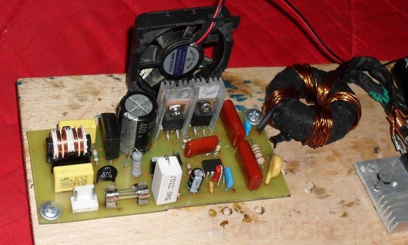
The need for trimming vіdmіnno, but for replacing deyakyh parts more drastic allow vychaviti from it 400 W and more. Chip IR2153 - self-clocking driver, which is developed specifically for robots in ballasts energy-saving lamps. Vaughn can be even a little slower, and it can be eaten through an intermediate resistor.
I will add storage
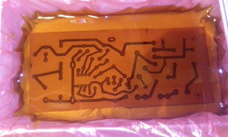
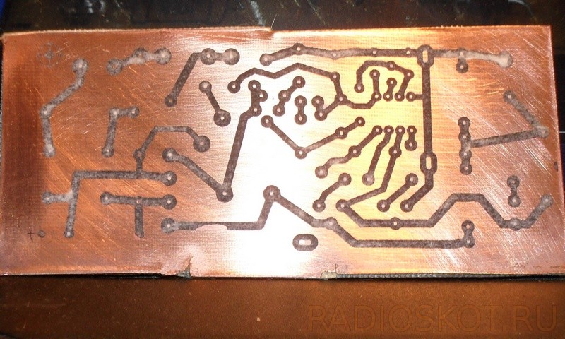
We need to pay for etching (etching, cleaning, drilling). Archive from PP.
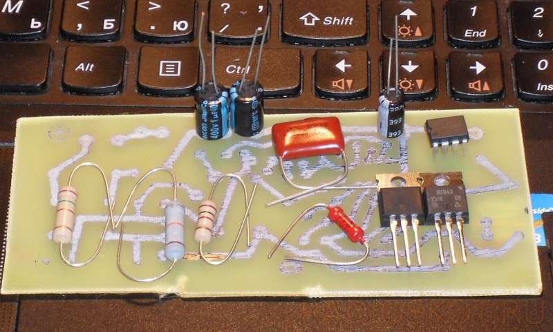
I bought a couple of daily details (transistors, irka and iron resistors).
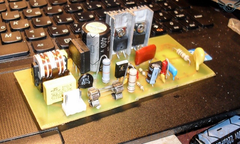
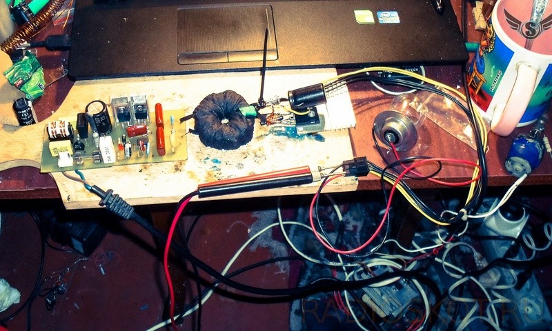
Before the speech mesh filter I took it out of the PSU from the disk program:

![]()

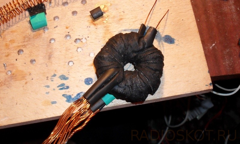
Now the best thing in IIP is a transformer, although there is nothing coherent here, you just need to be aware, how to wind it correctly, and all those. For the cob it is necessary to know what and how to wind, for which it is an anonymous program, the proteo is the widest and popular with radio amateurs - Excellent IT. We have our transformer.
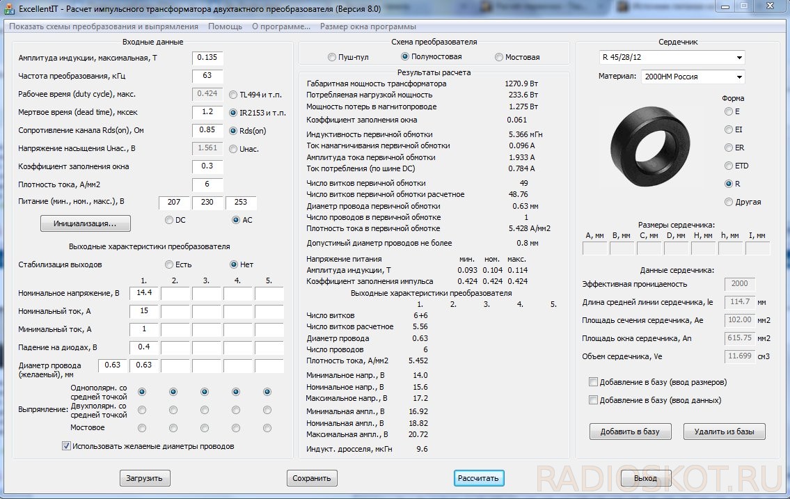
Like Bachimo, we had 49 turns of the primary winding, and two windings of 6 turns each (secondary). Motatimemo!
Transformer preparation
So, as we have a ring, it will be better for all facets of yogo under the hood of 90 degrees, and as a winding right on the ring, it is possible lacquer insulation, and yak naslіdok mizhvitkove KZ toshcho. To switch off this moment, the edges can be carefully sawed off with a file, or wrapped with cotton tape. If so, you can wind the primary.
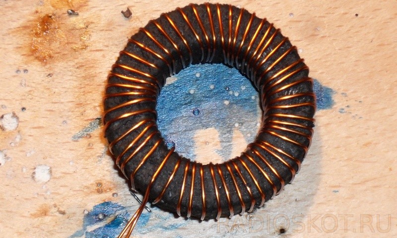
After that, as wound, once again wrapped with an insulating ring with a primary winding.
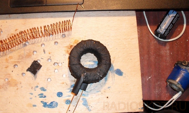
Let's sweat the beast for a second winding, it's true, a little more folding.
As can be seen from the program, the secondary winding can be 6 + 6 turns, that 6 wires. To do this, we need to wind two windings of 6 turns with 6 strands of 0.63 wire (you can choose by writing in the field with the wire diameter in front). Otherwise, it’s easier, you need to wind 1 winding, 6 turns with 6 cores, and then again the same one. In order to make this process simpler, you can, and wind up winding at two tires (bus-6 is alive with one winding), so we are uniquely skewed in tension (if you want wines, they can be but small, and often not critical).
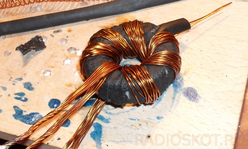
For bazhannyam, the second winding can be isolated, but not obov'yazkovo. Now, after that, the transformer is soldered with the primary winding to the board, the second one to the straightening, and the winding of the winding is unipolar from the middle point.

Vitrata midi is much larger, but less than the cost (in the case of less heat), and you can win only one single sample from the ATX power supply, which, having served your term, or simply not working. The first time the shoes are turned on, it is carried out with a light bulb included in the living room, in my mind, just by pulling the guard, and a plug is inserted into the lamp socket.
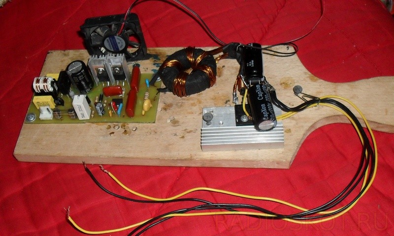
If the lamp burned out and went out, it’s normal, because the capacitor was charging, but I didn’t have this phenomenon, either through the thermistor, or through those that I put the capacitor at 82 microfarads at a time, or maybe all the places will ensure a smooth start. The result, even though there are no problems, can be included in the IIP measure. I have 5-10 A, lower than 12 V without having passed, then what is necessary for the life of the auto power supply!
- If the power is close to 200 W, then the resistor that sets the threshold for R10 is responsible for 0.33 Ohm 5 W. Yakshcho vіn bude in shaving or burn, burn all transistors, as well as a microcircuit.
- Merezhevy capacitor is selected from the distribution: 1-1.5 microfarads per 1 W of the block tension.
- In this scheme, the frequency of the conversion is approximately 63 kHz, and in the course of operation, singsongly, more quickly for the ring of the brand 2000НМ, the frequency is changed to 40-50 kHz, because the boundary frequency is 70-75 kHz on the same ring without heating. Do not chase after a great frequency, for this scheme and the ring of the 2000NM brand, it will be optimally 40-50 kHz. The frequency is too high to bring about commutation inputs on transistors and significant inputs on transformers, which means more significant heating.
- If you have a transformer and switches heated at idle with the correct folding, try to reduce the capacitance of the snubber capacitor C10 from 1 nF to 100-220 pF. The keys must be isolated from the radiator. Instead of R1, you can change the thermistor from the ATX power supply unit.
Axis of the end
Discuss the article
PRINCIPAL DIAGRAM OF THE IMPULSE LIFE UNIT
COMPUTER
THE ARTICLE IS PREPARED ON THE BASIS OF THE BOOK BY A. V. GOLOVKOV and V. B LYUBITSKY "FOOD UNITS FOR SYSTEM MODULES OF THE TYPE IBM PC-XT/AT"
Summing up everything that has been said, for the sake of completeness of the picture, we will introduce, as an example, a new description of the circuit diagram for one of the 200-watt impulse power blocks (Taiwan PS6220C) (Fig. 56).
The change of the tension of the tether is supplied through the PWR SW treadmill through the F101 4A treadmill, the changeover filters, made with elements C101, R101, L101, C104, C103, C102 and throttles І 02, L103 on:
output three-contact socket, up to which the display cable can be plugged;
two-contact rose JP1, part of which is found on the board.
3-pin JP1 changing voltage measures to be found on:
brukivku circuit rectification BR1 through the thermistor THR1;
primary winding of the starting transformer T1.
Figure 56. Schematic diagram of the electrical principle of the pulsed power supply unit PS-6220C
IMPULSE JEREL LIFE
On vіdmіnu od traditsіynih lіnіynih ІP scho peredbachayut gasіnnya zayvoї nestabіlіzovanoї naprugi on prohіdnomu lіnіynomu elementі, іmpulsnі ІP vikoristovuyut INSHI Metodi that fіzichnі yavischa for generatsії stabіlіzovanoї naprugi and the Same: efekt nakopichennya energії in kotushkah іnduktivnostі and takozh mozhlivіst visokochastotnoї transformatsії constant voltage. There are three types of schemes for generating impulse IP (div. Fig. 3.4-1): moving (output voltage higher than inlet one), lowering (output voltage lower than inlet one) and inverting (voltage change in polarity to inlet). As you can see from the little one, they stink less by the way of connecting inductance, otherwise the principle of work is left unchanged, but by itself.
The key element (sound to stop bipolar or MIS transistors), which works with a frequency of close to 20-100 kHz, periodically for a short hour (no more than 50% of an hour)
gives to the coil of inductance the same input of unstabilized voltage. Impulse strum. flows through the coil, ensuring the accumulation of energy in the magnetic field 1/2LI^2 skin impulse. In this way, the energy from the coil is transferred to the coil (either without a middle, from the diode's coils, which vibrates, or through the secondary winding with a distant rectifier), the capacitor of the external smoothing filter ensures the safety of the steel of the external voltage and stream. Stabilization of the output voltage is ensured by automatic regulation of the width or frequency of the passage of impulses on the key element (for zvorotny zv'azku).
So, if you want to do it well, the scheme allows you to move the KKD of the entire annex. On the right, in the fact that, in this situation, the crimson of the most important thing in the scheme is the daily power elements that cause significant tension. The key transistors work in the high key mode (tobto. the voltage drop is small) and it is less likely to increase the pressure to finish the short hour intervals (the hour of the impulse supply). Of course, for the increase in the frequency of transformation, it is possible to increase the tension and improve the weight and size characteristics.
An important technological advantage of pulsed IP is the possibility of building on their basis small-sized mesh IP with galvanic separation in the form of a mesh for living various equipment. Such IP will be without the bulky low-frequency power transformer behind the high-frequency converter circuit. Tse, vlasne, a typical circuit of a pulsed IP with a reduced voltage, so that the input voltage is reversed and the voltage is straightened, and the accumulating element is a high-frequency transformer (small-sized and with a high KKD), secondary winding what and znіmaєtsya output is stabilized voltage (its transformer also provides galvanic wiring with a wire).
Up to a small amount of impulse IP can be carried: high level Impulse noise on Vigivі, Temoki, Folding і low zadіinіst (especially with handicraft vigorous), Nechіdnіtn_nosuvnya expensive viscousisters whistles components, yaki at once by Nimesho, Email Email Enderstanding Easy to Lada "VIM Gurta" (at Cuoma, Yak Rule, can ). Fans of digging in the guts of outbuildings with a twist and a soldering iron when constructing wired pulsed IPs will have to be even more protective, shards of rich elements of such schemes are rebuyed under a high voltage.
Rice. 3.4-1 Typical block diagrams pulse tubes eating
Image:
2. Efficient stabilizer of impulse low folding level.
Efficient impulse stabilizer of low folding
On the elemental base, similar to the linear stabilizer in the described hole (Fig. 3.3-3), you can induce a pulsed voltage stabilizer. With the same characteristics, the wines have significantly smaller dimensions and a shorter thermal regime. The principle diagram of such a stabilizer is shown in fig. 3.4-2. Bid Stabilizer for typical scheme with reduced voltage (Fig. 3.4-1a).
When first switched on, if the capacitor C4 is discharged and enough is connected to the output push harder, Strum flows through IC line stabilizer DA1. Viklikane tsim strum drop voltage on R1 vіdmikaє key transistor VT1, which is here to enter the saturation mode, since the inductive opіr L1 is large and through the transistor flows a great strum. The voltage drop on R5 results in the main key element - the transistor VT2. Strum. growing L1, charging C4, with which, through the return link on R8, a record is

damage to the stabilizer and the key transistor. Energy, stored in the boiler, may be occupied. If the C4 voltage falls below the stabilization voltage, DA1 and the key transistor turn on. The cycle is repeated at a frequency of 20-30 kHz.
Lanzug R3. R4, C2 set the output voltage. Yogo can be smoothly adjusted in small boundaries, from Uct DA1 to Uin. However, even though Uvh is close to Uvh, it becomes unstable at maximum pressure and movement of the ripple. For suppression of high-frequency pulsations at the output of the stabilizer, inclusions of filters L2, C5.
The milking scheme is simple and most effective for this level of folding. All power elements VT1, VT2, VD1, DA1 may be small radiators. The input voltage cannot exceed 30 V, which is the maximum for the KR142EN8 stabilizers. Vipryamnі diodi zastosovuvat on strum not less than 3 A.
Rice. 3.4-2 Scheme of an effective pulse stabilizer on a simple element base
Image:
3. Attachment uninterrupted life on the basis of a high-frequency pulsed changer.
Power supply of uninterrupted life on the basis of a pulse stabilizer
On fig. 3.4-3 is recommended to look at the attachments for uninterrupted life of security systems and video warning based on a pulsed stabilizer used by charger. At the stabilizer, the system was introduced into the system for overheating, overheating, voltage drop at the output, short hum.
The stabilizer has the following parameters:
Input voltage, Uvx - 20-30 V:
Vihіdna stabilized voltage, Uvix-12B:
Nominal strum vanity, Iload rated -5A;
Strum spratsovuvannya system zahistu vіd revantazhennia, Izasch - 7A;
Voltage spratsovuvannya system zahistu vіd overvoltage, Uvih zah - 13 V;
Maximum battery charging jet, Izar battery max - 0.7 A;
Riven pulsation. Upulse - 100 mV
The temperature of the spratsovuvannya system for protection against overheating, Тzasch - 120 С;
Quickness of switching food from the battery, tswitch - 10ms (relay REM-b RFO.452.112).
The principle of a robotic impulse stabilizer in the described extension is the same as in the stabilizer presented above.
Attachment of additions to the charger, vikonanim on the elements DA2, R7, R8, R9, R10, VD2, C7. ІС voltage stabilizer DA2 with strumu R7 dilnik. R8 is between the maximum cob charge charge, R9, R10 sets the charge voltage, the VD2 diode protects the battery from self-discharge due to the life voltage.
Protection against overheating of vicorist as a temperature sensor and thermistor R16. When the protection is activated, an audible signaling device is turned on, picking up on ІС DD 1 and at the same time the voltage is switched on from the stabilizer, switching to the battery from the battery. The thermistor is mounted on the radiator VT1 of the transistor. Precisely, the construction of the level of temperature protection is supported by the R18 support.
Voltage sensor pickup on the dilnik R13, R15. the R15 support is used to establish the exact level of protection against overvoltage (13). When the voltage is changed at the output of the stabilizer (at the time of the output of the rest of the fret), relay S1 switches on the voltage output of the stabilizer and connects to the battery. When the power supply is turned on, relay S1 will switch to the “for locking” station - that is. connect the charge to the battery.
A circuit is induced that does not allow electronic short circuiting for the battery. this role is played by a fusible zapobіzhnik at the lancius of liveliness of the venture, repayments for the maximum strum, which is saved.
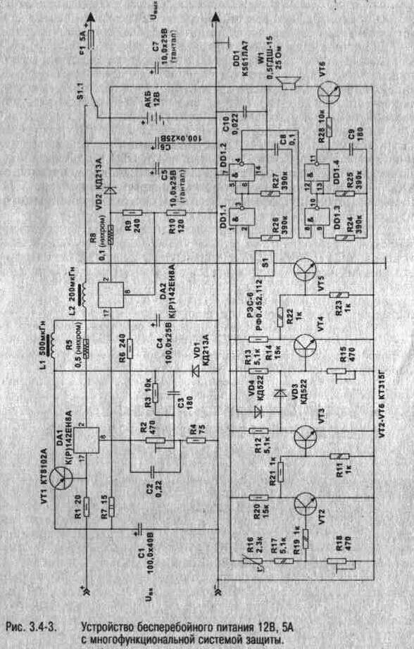
Rice. 3.4-3 Scheme to add uninterrupted living 12V 5A from a rich functional system
Image:
4. Dzherela life on the basis of a high-frequency pulsed converter.
Dzherela living on the basis of a high-frequency pulsed converter
To finish often when constructing outbuildings blame zhorstki vimogi to the core of life. In this way, a single output is the stosuvanya IP on the basis of high-voltage high-frequency impulse shifters. they are connected up to ~220 without blocking the overall low-frequency step-down transformer and can provide great pressure at small sizes and heat transfer.
Structural diagram of a typical pulsed re-energizer in the form of an industrial line is shown in Fig. 34-4.
Input filter of assignments for preventing the penetration of impulse transitions at the merger. Power keys ensure the supply of impulses high voltage on the primary winding of a high-frequency transformer (one

double circuits). The frequency and the trivality of the pulses are set by the generator (sound to control the width of the pulses, or, more likely, the frequency). At the input of transformers for a sinusoidal signal of low frequency, pulse IP, a wide-width extension is installed, which ensures efficient transmission of tension on signals with slow fronts. The price is imposed on the type of magnetic circuit and the design of the transformer. On the other side, with the increase in the frequency of the necessary expansion of the transformer (from the conservation of tension, which is transmitted) is changed (the current materials allow the use of other transformers with a suitable CCD at frequencies up to 100-400 kHz). The peculiarity of a variable voltage rectifier is that it is stuck in the new not the strong power diodes, but the Schottky diodes, which are conditioned by the high frequency of the voltage, which are rectified. Exhaust filter smoothes the pulsation of the exhaust voltage. The voltage of the return link is equal to the reference voltage and then energized by the generator. To give respect to the presence of galvanic decoupling at the lance of the inverted connection, which is necessary, as we want to ensure the decoupling of the electrical voltage from the mesh.
In the preparation of such IPs, serious vimogi are blamed for components (which promotes their variability, similar to traditional ones). First, it is necessary to use the working voltage of the diodes of the rectifier, the capacitors of the filter and the key transistors, as it is not guilty, but less than 350 V, in order to avoid breakdowns. Otherwise, high-frequency key transistors (operating frequency 20-100 kHz) and special ceramic capacitors (primary oxide electricity at high frequencies will be overheated through their high-frequency induction) are to blame.

activity). I. thirdly, the frequency of the high-frequency transformer, which is determined by the type of magnetic core that is stuck to the core (as a rule, toroidal cores are twisted) is to blame for the working frequency of the switch.
On fig. 3.4-5 pointed principle diagram classical IP on the basis of high-frequency changer The filter, which is composed of capacities C1, C2, SZ and chokes L1, L2, serves to protect the line from high-frequency transitions from the side of the changer. The generator of impulses behind the self-oscillatory circuit and impulses from the key cascade. The key transistors VT1 and VT2 operate at the opposite phase, vibrating and curving along the curve. The start of the generator and the operation of the robot are ensured by the transistor VT3, which works in the avalanche breakdown mode. With the increase in voltage C6 through R3, the transistor fires and the capacitor is discharged to the base VT2, starting the generator robot. The voltage of the return link is taken from the auxiliary (III) winding of the power transformer Tpl.
Transistors VT1. VT2 is installed on radiator plates less than 100 cm^2. Diodes VD2-VD5 with a Schottky barrier are placed on a small radiator 5 cm^2. Data of throttles and transformers: L1-1. L2 is wound on rings with ferita 2000NM K12x8x3 for two darts with a PELSHO 0.25 dart: 20 turns. TP1 - on two rings, folded at once, ferit 2000NN KZ 1x18.5x7;
winding 1 - 82 turns with PEV-2 0.5 wire: winding II - 25+25 turns with PEV-2 1.0 wire: winding III - 2 turns with PEV-2 0.3 wire. TP2 is wound on a ring with ferita 2000НН К10х6х5. all windings with winding wire PEV-2 0.3: winding 1 - 10 turns:
windings II and III - 6 turns each, the windings (II and III) are wound in such a way that they occupy 50% of the area on the coils without sticking and not overlapping one another, winding I is wound evenly along the entire ring and insulated with a ball of varnished cloth. Winding filter coils L3, L4 on ferrite 2000NM Up to 12x8x3 wire PEV-2 1.0 number of turns - 30. In the capacity of key transistors VT1, VT2, KT809A can be installed. KT812, KT841.
The ratings of the elements and winding data of the transformer induction for the winding voltage of 35 V. In case of need for other operating values of the parameters, the next change is the number of turns in the winding 2 Tr1.
A scheme is described for the number of stale components, zooming in on exercises, and limiting the number of stagnant components. The price and low level of stabilization of the output voltage, and the unstable non-stationary work, and the low output stream. However, it is entirely suitable for living the simplest constructions of various tightness (with congestion of vital components) like: calculators. lighting fittings etc.
Impulse stabilizer with a key MIS transistor for reading the struma.
Miniaturization and improvement of the CCD during the development and design of pulsed dzherel zhivlenneniya spriyaє zastosuvannya new class of conductor inverters - MIS-transistors, as well as: field transistors from an insulated gate, integrated circuits for controlling key elements. All these elements are available on the domestic market and can be used in the design of highly efficient living heaters, refurbishments, ignition systems for internal combustion engines (IDF), systems for starting lamps. daylight(LDS). Great interest among retailers is also possible to find a class of power devices under the name of HEXSense - MIS transistors for reading the struma. The stench is with ideal elements, which are mimicking, for impulsive dzherel zherel zhivlennya s preparing management. Possibility to read the strum of the key transistor can be vikoristan in pulsed IP for the reverse connection of the strum, which is necessary for the pulse-width modulation controller. It is possible to simplify the design of the dzherel zhivlennya - switching off the new stream resistors and transformers.
On fig. 3.4-7 shows the circuit of a pulsed dzherel zherel zhenernija 230 watts. The main working characteristics are as follows:
Input voltage: -110V 60Hz:
External voltage: 48
Strum input: 4.8 A:
Mic frequency: 110 kHz:
KKD under full quest :
78%;
KKD at 1/3 advantage: 83%.

The circuit is based on a pulse-width modulator (PWM) with a high-frequency switch at the output. The principle of robotic action is in the offensive.
The control signal for the key transistor comes from output 6 of the PWM controller DA1; The life of DA1 is secured by the lancet VD5, C5, C6, R6. Resistor R6 is intended for supplying a voltage of life for an hour when the generator is started, in the future, a return link for voltage through LI, VD5. Tsey zvorotny zv'azok come out of the additional winding of the outgoing choke, which works in the mode of the vortex move. Crim of the generator's life, the voltage of the return link through the lance VD4, Cl, Rl, R2 is fed to the input of the return link of the voltage DA1 (viv.2). Through R3 and C2, compensation is ensured, as a guarantee of the stability of the loop of the inversion link.
On the basis of the circuit diagram, it is possible to generate impulse stabilizers and with lower output parameters.
Module 3
Chapter 4
impulse voltage conversion IVEP
Often, when designing electronic appliances, many times they are blamed for the weight and size indications of the secondary power supply (IBEZ). At Tswy Vipadka єdimy Vipyavona є єVosuvnya ІVep on the basis of the viscous spectacles of the Impulse, yaki p_devuvachіv's dips, yakі p_devyuyu ~ 220 V frequency stream of 50 Hz Abo 115 V І frequency stream 400 Hz without groaving the overall low-frequency transformer, and shuttering frequencies 20-400 kHz, and can provide greater pressure at small sizes and heat transfer. Such zherela zhivlennya may be an order of magnitude better weight and size indicators in line with linear ones. ІВЭП with a pulsed high-frequency conversion, it is possible to improve the richness of the characteristics of the outbuildings, which live like these dzherel. Pіdstavami for zastosuvannya іmpulsnih ІVEP on osnovі visokochastotnogo Peretvoriuvach mozhut Buti: ymovіrnіst Oscillations vhіdnoї naprugi in the furrows of ~ 100-300 V, mozhlivіst stvoryuvati ІVEP of potuzhnіstyu od desyatkіv watt to hundreds kіlovat on whether SSMSC vihіdnі naprugi, The options visokotehnologіchnih rіshen on osnovі ІS that other components.
The transition to the most important momentary energy of life is about low technical and economic factors, the most important of which are:
· Dzherela transformerless living (DBZH) potuzhnistyu up to 500 W may have the same weight and size characteristics compared with analogues, prepared on the basis of mesh transformers;
· The windings of the transformers of the HF colivane of the DBZH may have a greater high width of the struma, when they are prepared, they are richer than the colored metal, which leads to a decrease in the vitrat on the vibration and on the outer materials;
· High induction and small amounts of materials used in the cores of high-frequency transformers make it possible to create a DBZh from a high CCD, which exceeds 80%, which is unattainable in the case of high-frequency dzherela;
· wide range of possibilities with automatic adjustment of the ratings of the external secondary voltages for assistance on the primary lances of the high-frequency switch.
Let's take a look at some of the examples of structural diagrams for inducing a DBZH with a primary spring of 220, 50 Hz.
On fig. 74, a the block diagram of the pulsed dzherel zhivlennya, which has been beaten by the traditional scheme, is presented.
Vipryamlyach, a filter and a stabilizer, which is in the secondary lance of this dzherel of life, inspired on the basis of the knots, which are zapped in the splendid dzherel of electric life. The names of the nodes of the curve are recognized and do not require explanation. The way of realization of the stabilizer (linear or pulsed) in this case is not as important for equal presence as a small functional unit. The second line of electric power in other variants of the vykonanny dzherel can be supplemented with one more filter, which is installed between a stabilizer and an advantage. The main knots of the primary lancet є: inlet filter, straightener mesh tensionі HF conversion of the rectified voltage of life with the transformer TV.
The need for a variable inlet filter is explained by the fact that, first, this filter is to blame for the use of sharp short-hour haircuts of the voltage of life and pulse shifts, vibrating the robot around impulse outbuildings(HF changeover) or blame at the moment of connection, or switching on at the time of the sum of the connections. In another way, the filter is guilty of effectively using crossovers, which penetrate the fence without intermediary from the vitality, which victorious.
In the impulse dzherel life (Fig. 74, a) there is a cascade of high-frequency conversion of a self-oscillating type, the auto-cooling mode of this type is less than the values of the nominal values of the power elements and is not regulated.
Dzherelo zhivlennya, vikonans behind the scheme, induced in fig. 74, a, you can additionally turn on the rewiring sensor, which will either go to the stabilizer, or to the HF switch, blocking the robot until the moment the cause of the malfunction is detected.
With the correct selection of the elemental base, it was dzherelo, prepared for this scheme, it is simple to implement - it has a head start, prote through a low CCD is rarely achieved. Changes in the KKD are due to the increase in the number of secondary channels of various voltages, skin shards and the need for a voltage stabilizer. With a hundred short circuits, the sensitivity of self-oscillators, connected with the IP power stage, can be even higher, up to the magnitude of the bias. Її zmіna can bring to the sight of HF colivation and instability of the robotic life of a similar kind.
Structural scheme of the tethered dzherel zhivlennya, pobudovaniya z urahuvannyam optimal principle of regulation of output voltage, is shown in fig. 74, b.

Fig.74, b
Principal importance of this structural scheme is in the form of a forward field in the presence of the stabilizer of the secondary voltage. In addition, before it was added a vimiryuvalny lance that sets the generator, the control circuit, as well as changing the functions of the cascade of the HF conversion. The power cascade works in the mode of subduing the tension of coliving, which is necessary for the schemes of healing. Yogo navantazhennyam є HF transformer. Here, the HF turn can be called the sequence of the advancing nodes: the generator, what is set, the control circuit, the HF power supply, the HF transformer ( TV). Dzherelo, Vikonan is similar to the block diagram shown in fig. 74, b, simultaneously zdіysnyuє two functions - transformation and stabilization of the voltage. The control circuit turns on the pulse-width modulator and, for the most part, selects the ROM operation mode. Vihіdna napruga circuits keruvannya maє the form of rectilinear іpulsіv. Changes of trivality, pauses between them, regulate the supply of energy in the second lansy with impulses. The external parameters for the robotic control scheme are the signals of the pardon, which should be in the vimiruval lance, in which the comparison of the reference value of the voltage with the real, present at the given moment on the vantage is carried out. At the signal of the breakup, the control circuit changes the interruption of the pause between pulses at the bіk її zbіlshennya chi change, fallow, according to the magnitude of the deviation of the real value of the voltage, vіd rated. Zocrema, before the control scheme, you can enter the vuzol for the cascade of ROZUM in the event of a short chime.
The presence of the SHIM of the transmitted voltage presents a lot of power to the parameters and induces a filter that smooths out the rectified secondary voltage. The first element of this filter after the rectifier may be the coil of inductance at the skin channel of the secondary voltage.
Shown in fig. 74, b the scheme, which is the structure of a single-channel living system, in reality, there may be, as a rule, a sprinkling of secondary channels with different navantage building.
On fig. 75 shows a block diagram of a multi-channel pulsed voltage changer. Vimiryuvalny lansyug in such cases is connected to the channel with the greatest comfort. Stabilization of other channels is carried out with the help of other stabilizers and methods of regulation based on the interplay of magnetic fluxes.
In other cases, the circuits of external filters are installed, which run on the magnetic core, which is vital for all external channels. Voltage rebuilding through non-main channels can be carried out in a small range and for apparently small voltage changes. When describing practical schemes for the implementation of IP power supply stabilization of the secondary voltage, reports will be reviewed at the same time on a number of channels.
The peculiarity of a variable voltage rectifier is that it is stuck in the new not the strong power diodes, but the Schottky diodes, which are conditioned by the high frequency of the voltage, which are rectified. Exhaust filter smoothes the pulsation of the exhaust voltage. The voltage of the return link behind the auxiliary system is equal to the reference voltage and then the retail signal is fed to the pulse-width controller (modulator). The voltage of the direct current pulses of high frequency from the output of the PWM controller is applied to the input of the transistors in the narrower extension, which is the work of the high-frequency voltage suppressor. The PWM modulator in this hour is built on a microcircuit, for life, as it is built up to a life-sustaining appendage. As a rule, in the lace reworkings, there is a galvanic rozvyazka of the lancet of the zvorotny zvezku. It is necessary, as it is necessary to ensure the release of the output voltage from the mesh.
The main node of the voltage reversal is the first power part (pulling out cascade - tension relief).
Vihіdnі cascades of all reversible voltages for the number of impulses that are transmitted to the voltage, in one period can be divided into two great classes: single-cycle and double-cycle. If one impulse is transmitted, then the conversion is called single-stroke, if two, then two-stroke. KKD of the first lower, lower than others, that is why single-cycle vicor is used for the creation of IVEP at a power of less than 10 ... 200 watts. Two-stroke permutation allows you to take away the great exhaustion for the high CCD. One-cycle switching can be for a direct-running (with direct switching on of the diode) or a reverse-running circuit (with a turning-on diode). Two-stroke reversing can be bridged, nap_bridge or from the middle point of the primary winding of the transformer.


