Voltage stabilizer with strumu regulation. Adjustment stabilizer of the voltage with regulation of the change of the output struma. Scheme of a stabilizer with a regulation block for living
11
Regulating voltage stabilizer
A simple circuit, with average parameters, based on transistors with great powers. The bula is crushed for its needs like a laboratory.
Often I had to deal with repairs or launch various schemes, for which it is necessary to simply mother them to live 3V, 5V, 6V, 9V, 12V ... I just shukav anything is appropriate. At the head there were blocks of life such as calculators, tape recorders, accumulators, batteries. Sometimes it was quiet, that in the middle of the day the dzherelo did not give great strums, in such a rank ryatuyuchi less in the face of the wicket. Zvichayno robbing one-two-transistor stabilizers to solve this problem, but the results were not satisfied. Here, on another whil of inspiration, those with whom I want to share have been born.
Check the dossi during repairs and the launch of the outbuildings, as it should be output voltage extremely. And also in case of an unexpected zastosuvannі - re-verification of stabilitrons, charging finger batteries, just like a dzherelo stable struma. In such situations, the obviousness of wanting a voltmeter at the exit is already obvious.
The simplest stabilization block of life
Capacitors after two integrated circuits serve as the head rank. Change the inductive effects of the integrator and any other active radiators in other components of the other circuit. Therefore, it is recommended to install their instructions from the integrated radiator.
This type of stabilized dzherel zhivlennya, only through vikoristannya guessing more than two integrated circuits, allows. Be sure to protect against short strums. Do not use additional electronic components for further voltage stabilization.
Scheme
The attachment was designed for the output voltage of 1...12V and the regulation of the output stream in the range of 0.15...3A. For good results, putting transistors with power over 500 (taken from the MTs-31 board of the 3ust TV), and storage control - close to 10,000 (for example, the vimiruvach is not a problem - taking from the TFR module of the TV 2ust, raster correction).It is important that by living the scheme car battery when you know the data.
Further, having put a transformer and a diva type 3A at 12V, it became impossible. The voltage dropped at the exit of the straightener. Who else tsikavo - closer to the scheme.

Integrated line controller with control of the stream, which can control the short circuit of the stream, the temperature and the maximum input voltage. Life voltage - tse voltage 230 V a.c. With a minimum external pressure, the vitality can only give an external signal 1A, so that the tension, which rises, will be too high and too thirsty for too much heat.
Vіn in the first line of assignments for the last, and then the linear ones, but also can be vikoristovuvatsya like a commutator controller. Vіn mає vіn mіshnіy dzherelo vodnoї vodka, which can be vikoristany for regulation operations, zokrema є є voprosa 15V, which is given by name through a special pin integrated circuits.
Scheme of the voltage stabilizer with the regulation of the exchange of the outlet stream
Also, X1 is supplied with a minus voltage, and X2 is taken stabilized and surrounded by a free stream of voltage. In short, VT3 is a control, VT4 is a comparator and a signal for the break of the voltage stabilizer, VT1 is a comparator and a signal for the break of the stabilizer of the outgoing stream, VT2 is a sensor for the presence of an exchange of an outgoing stream. The expansion of the voltage stabilizer option was taken as the basis.
Integration ensures the miraculous regulation of lines and voltage, so that the pulsation and noise of the input voltage are suppressed, and also the change of the stream of voltage is dipped, not creating noise on the output voltage. The maximum strum can also be adjusted in the presence of a designated body, changing the value even more.
The first scheme, so that the voltage regulator 7 with a maximum voltage of 3, less than the maximum voltage of the input stream 2A and a short flicker, looking like an approaching rank. It’s true, if the input voltage becomes 35, if it’s less, the lower tension is not 56, but it’s less.
Outline scheme with a fixed tension and a zakhist along the strum
It has been slightly changed, so that you can change the voltage at the largest possible distances, and remove the blocking of the stabilizer. Addendum R8, to enable the robot to exchange the external stream at VT1. Additions R7 and VD3 for setting between the change of output voltage. Capacitors C1 and C2 will help to reduce the ripple at the output.
Another diagram, but itself: a voltage regulator 7V-7V with a maximum stream of 2A and a short hum looks like an offensive rank. The rest of the diagram is with a stabilized zherel of life with a minimum voltage of 7 V and a maximum strum 2A іz zahistom, but with a maximum voltage, which should lie like a vicorous Zener diode, tobto.
Let's marvel today, to implement our first scheme. We worked out in this state that it is possible to equalize with the lung, as it is charged and discharged, and we worked out that this function can be victorious to vibrate the voltage. Let's see what is happening.
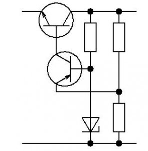
Now let me go through the explanations on another stake (div. pershu scheme). When a negative constant voltage between 9 ... 15V, a strum appears at the lance R2-VD2-R6-VD1. A stable voltage appears on the stabilizer VD1. Part of the voltage is applied to the VT4 base, which is the result. Yogo strum collector v_dkrє VT3. Strum collector VT3 charge C2, and through the dilnik R9, R10 part of the voltage C2 (it’s out) is on the VT4 emitter. This fact does not allow the external voltage to increase more, lower subwar (Vbasi VT4 - 0.6V). The answer to that, dіlnik R9, R10 for two. Since the voltage is stable on the basis of VT4, the output will also be stable. Ce working mode. Transistors VT1, VT2 are closed and do not burn.
The red graph is the output voltage of the vibrating bridge, and the blue graph is the voltage on the capacitors, the values we know from the capacitor. Just as soon as the first charge starts, the capacitor charges by itself, to bring the voltage to the maximum value, if the charge drops, the capacitor properly starts to charge, but the building’s discharge is even a little, so I’ll renew it, recharge the charge, recharge the capacitor yogo of the maximum value.
In practice, the change in voltage 12 reaches the peak, which reaches close to 17, and it’s exactly the same value, as if you would take the voltage after vibrating. Component may 3-pin input pin 1, may need to be larger high voltage, lower voltage, which grounds contact 2, make the connections from the ground, so it is negative, and the outer winding 3, for any trace of drawing the tension, set on the value bar.
Let's get excited. Z'appear strum navantazhennya. V_n flow along the lance R2, E-K VT3 and farther ahead. R2 works as a strum sensor. In proportion to the stream, the voltage settles on the new one. The voltage is mixed with a part of the voltage taken for the help of R5 and VD2 and is added to the basic transition VT1 (R3 is purely for the exchange of the base of the VT1 when throwing and defending in such a rank of VT1) and if it becomes sufficient for the output of the VT1, apply to enter the exchange mode external struma. Part of the stream of the VT4 collector, which earlier reached the VT3 base, immediately passes through the VT2 base-emitter transition to the VT1 collector.
Due to the great coefficient of transistor strength, the voltage of the base-emitter VT1 is approximately 0.6V. Tse means that the voltage on R2 will be constant, so the strum through the new one, and then through the tension. The engine R5 can be used to select the strum water from the minimum to the maximum 3A.
In order to show the mode of submerging the strum of water and VT2, ignite the light HL1 with your strum of the collector of wines. It should be understood that the exchange of the struma is a priority over the “stability” of the external voltage.
This controller is a part of the family of controllers, where the remaining two digits of the code indicate the current voltage. Tsya the rest of the boundary can be significantly lower, the shards will lie in various factors. Forgive me rozsіyuyutsya at the spec, and we already bacheled at the stats, scho we can calculate the value.
To that, in order to save too much heating, the cream of the radiator, which was made earlier, we can change its intensity, and for which we have є 2 alternatives, or we change the energy supply, or we are to blame for being satisfied with the smaller strum. Tse explain why tsі 2A-maximi are stunned, stench is theoretical, but it’s also practical to lie down depending on how much input voltage and how well the regulator cools down.
At the exit, I’ll put a voltmeter, and if the axis is needed on the strum stream, I’ll just quickly leave the tester in the ammeter mode and, for the help of R5, I’ll try the bag.
Details
The circuit is simple, but everything is well founded on the great powerful transistors (more than 500). And VT3 vzagalі folded. There are no letters in the names of transistors, but maybe everything can be written. I have all "G". Golovne - stronger and smaller coils. They write to the doctor that some of the letters “Ku” may be 200, but my all are more than 600. Changers got caught by group A. For VT3, a radiator is needed. I put some kind of bov i vlіz at the body. The maximum reliability should be ensured only by the radiator, insurance for the expansion of tension, which is more expensive Multiply the input by 3A, tobto. 30...50W.I think few people need 1V at 3A for a long time, so you can safely put a radiator at 2 ... 3 times less.
VD2 and VD3 are 0.6V voltage plugs. You can use other silicon diodes. R4 - deshcho zsuvaє threshold, if you are sleeping light. If wine is burning, it means that there is a place for the depletion of the outer stream. R1 simply surrounds the stream of light. Potentiometry is possible with a larger nominal value (at 2...3 times). R8 can be changed (here up to 4k), so the VT3 transistor cannot be pulled stronger.
It is obvious that the circuit is to blame for the changeable voltage of 12 to 24, which, obviously, cannot be directly connected up to 220 V, but it is to blame for connections for an auxiliary transformer. Zavdyaki transformer we can connect our circuit to fringing tension, Obviously, by connecting the 220-volt socket to the home socket, and the 12-volt output at the input of our circuit. Then we can add a light, which indicates that our lifeline is noted and there may be connections, and, perhaps, insert 2 screw clamps to ask for the connection of our circuit.
With a hand-me-down payment - like a head in simple circuits, which are prepared in a single copy. Bula fee for something else regulated stabilizer voltages, the parameters of which were not vlashtovuly. Vaughn was turned into a mock-up and on a niy zibrana given scheme. Resistors vikoristanі 0.25 W (possible і 0.125) - I don’t know much about it. At 3A (as your vipryamlyach їх give) - the factory rattle R2 (2 W-a) will be set harder (5W) between and varto. Electricity - K50-16 at 16V.
Yakist electrical pressure can contribute to the productivity of the system and therefore it is necessary to adjust and stabilize, so that you can fix any defects that can damage batteries. Strength is of paramount importance for ensuring the maximum productivity of systems and the elimination of defects, which can expand in the distance, like stutters, harmonics, and impulses and shifting. In all circuits on other boards, in fact, capacitors are used to introduce phase failures and inductances, to introduce phase jams, and there are tabs to eliminate hundreds of them.
There is no such thing as a folded transistor - "fold" it for some reason. Correct from KT817 + KT315, with letters “B” and dal. (However, I still can’t get stronger at VT3, I would change R9 and R10 to 200 Ohm and R8 to 2 kOhm).
Transformer, rectifier and filter capacitor - Vashі. The stench is not less important, but I would like to tell you about such a larger-less universal stabilizer. (I have a 10-watt trans at 10V / 1A replaceable, the stars of taking blocking places at 1A, and 4000uF / 16V electrofilter. It's disgraceful, then everything fits into the case.
Everything was well designed, changing the phases of the voltage and the struma is to compensate for the lances, or, in fact, the thermal cohesion can create electromagnetic couplings, as if unique to the designers and create distortions and noise at the sight of peaks in the voltage and the phases of that stream, the building of the other.
For this reason, we need to adjust the coefficient of tension, or the phase cut between the two carrying the voltage and struma, in order to maximally change yoga. Schemes for correcting the coefficient of tension are the main ones, shards of tension often come from a readily accessible barrier with an already strained tension and a strum, and are also filled with irregularities.
It is necessary to note that the arrow indicator (there are no indications in the scheme) for an additional switch, you can use it as a voltmeter and as an ammeter. In the first one, the bachimo will lose the strain, in the other, the strum will go out.
together
I have a variety of attachments for me at the “all in one” warehouse: distribution (hoch and unipolar) living block, frequency and audio frequency generator (sine, square, trikutnik). The scheme is taken from the Radio magazine. (We don’t call for what we wanted to. First of all, we made too many “unauthorized” changes – especially in the element base – by setting it to mav.) It is obvious that the voltmeter head can be used as a frequency indicator in the frequency meter. When the alternator is switched, the frequency counter shows the frequency. Є th exit variable voltage 6.3V and 10V, for every fluctuation.The case, which can be seen in the photograph, is not much more than that, to repeat it. And in a flash: everything was conceived there, like a mirror image, but having bent the front panel in the wrong way. I'm roztroїvsya and not becoming yoga nіyak embellish.
Therefore, it is necessary to filter and adjust the pressure before the її vikoristannym for the regeneration of lithium-ion batteries, which are recharged, as they supply the most current electronic vibrations. As for batteries, there are no control schemes, like a little protect their external values of voltage and struma, and then avoid malfunctions, uniqying a further extension of defects.
Analog power allows you to reduce energy efficiency by 90% more than digital controllers. In practice, the first chip is to replace the high input impedance substation, which will reduce the battery discharge charging strum and then we’ll diferential podsiluvach, which vimiryu yogo mitteva tension.
Filey
Viktor Babeshko repeating the design, adding his print version and photo.LayOut file: ▼
Considering the shortfall of fusible zapobіzhnikіv є їх disposability, the need for further replacement of the manual for another zapobіzhnik, repayments on the same stream of protection. In most cases, if there is no help in hand, vicorist defenders on the other stream, or moreover, put self-reliant (surrogate) defenders, or just massive bridges, which in turn negatively affects the reliability of the robotic equipment and is not safe in the future.
I will secure an automatic bagatorazovy zahist and I will add it at once, you can send it to the swedcode for the account of the electronic guards. The annex can be divided into two main classes: the first of them are self-sustaining life following the explanation of the causes of the accident, the other is less than the introduction of people. In the house there is also an annex with a passive zahist - in emergency mode, the stench is less likely to indicate a light or a sound signal about the presence of an unsafe situation.
For the protection of radio-electronic attachments in the strum shift, sound the vicorist resistive or strum conductor sensors, included sequentially in the lance of the strum. Just like a drop in voltage on the strum sensor to shift the tasks equal, spratsovuє zahisny pristry, which includes an interest in the life. The advantage of such a method is to defend those who can easily change the size of the struma spratsovuvannya. Most often reach for the help of the sensor strum.
Inshim efficient method Zahist navantazhennya є obezzhennya of the magnitude of the boundary struma through it. Navіt for nayavnostі v lanzyuzі vantagenja short zamikannya strum for zhdnyh obstavin not zmozhchit tasks rіven and shkodity vantagennija. For the exchange of a boundary struma, vicorist generators and a stable struma are needed.
Simple schemes automatic zahistu radio-electronic attachments in the form of strum shifting are presented in fig. 5.1 and 5.2. Robot attachments of this type (strumu stabilizer based on field effect transistor) Reportedly reviewed earlier at branch 5 (book 2). Strum navantazhennya when using such an intermediate device, it is not possible to transfer the cob strum to the drain of the field-effect transistor. The value of this stream can be set by choosing the type of transistor, for example, for a KP302V type transistor induced on the circuit, the maximum stream through the bias should not exceed the value of 30 ... 50 mA. It is possible to increase the value of this stream by parallel switching on a number of transistors.
The module accepts an input of ± 25 V and can drive up to 25 A of the stage light, staging two mosets as a shackle diode between a collector and an emitter. 
Topic of the course: voltage stabilizer design. PROCEDURE FOR PROCESSING THE NAVIGATION STABILIZER. Life voltage change.
Enter the annex of life, which will vicorist the tightness of the meshes of the distribution of electricity. electric power of electronic control, є electronic changeovers fast strumu. Crimean conversion stinks may be zavzhdi vykonuyutsya. stabilization of the strained voltage and zahistu in the extreme values of strum and strain. The transformation of the changeable voltage is constantly built up by straighteners, stabilization of stabilizers and zahisty lancers and zahisnymi elements.
Rice. 5.1. Exchange of the boundary struma for the supply of a field-effect transistor
Rice. 5.6. Scheme of a voltage stabilizer with sound indication of voltage
Under the hour of the work of the stabilizer, the strum is expected to pass through the strum sensor R1, creating a new voltage drop. While the strum is small (when the value of the resistor is not more than 0.3 A on the circuit), the transistor VT1 closes. In the world, the growth of the stream is slowing down, obviously, the increase in voltage on the resistor, the transistor is approaching the threshold of voltage. If the voltage between the base and the emitter of the transistor VT1 reaches 0.7, the voltage drops and, with a further increase in the struma, go over to the station. When the transistor is turned on, the voltage is straightened to go to the acoustic signaling device and bring it into action.
A sound signaling device for VT1 transistors can be used for life.
Electronic zapobіzhnik for lansyugіv postіyny strumu and one-hour voltage stabilizer can be beaten by the circuit shown in fig. 5.7. On the first two transistors (VT1 and VT2), a voltage stabilizer was selected for the traditional circuit, however, in parallel with the stabilizer diode VD1
The relay cascade on transistors VT3 - VT5 is switched off from the data stream on the resistor Rx. When zbіlshennі ponad given him struma in navantazhennі tsey cascade spratsyuє and shuntuє sta-pitron. The voltage at the output of the stabilizer falls to non-(reading value.
One block of life sounds including all three types of nodes, which can be used. repeat sprat times. Possible options with kіlkom schemes for blocking living snake struma. On the little one 1 two widest ones are shown. On fig. 1a shows the life of the fence. the transformer is a one-time conversion of energy. And here is the tension.
At the gallery, health protection and eating 2. In both versions, there are living schemes, control schemes, protection and signaling. yakі mayut raznu skladnіst zalezhno vіd їkh prichennya that vymog. In all outbuildings, the energy is directly energized from the dzherel to the spozhivacha - from tsom. the sequence of didactic mirkuvans is explained. However, with їх rozrobtsі vihіdnimi і є danі spozhivacha ta nastrіy. Tse shy away from the reverse order - look like a spozhivach to the net.
5.7. Scheme of the electronic zapobіzhnik - voltage stabilizer postіyny strum
To unlock the circuit, press the SB1 button briefly.
Vikoristannya automatic vimics the need for -! Change the timer functions and change the timing when short flicker follow the scheme in fig. 5.8.
Avtovimikach navantazhennya pratsyuє offensive rank, short-hour pushing the button SB1 capacitor C1 is charged from the dzherela zhivlennya through the resistor R1. One hour atuє key (keys) / SHO / 7-switch (DA1), ensuring that it turns itself on push transistor VT1. Like the SA1 key of openings, it is used for the ep scheme. Capacitor C1 is discharged through a lance of inclusions-1 in parallel with resistors R3 and R2. If the capacitor C1 is charged, it will automatically connect to the dzherel<ия и отключит нагрузку.
When the SA1 jumper is closed, the timer does not work. The 7-switch is blocked by supplying a high level voltage to the key input (enter) through the diode VD2 and resistors R4, R5. Scheme of zahistu dzherel zhivlennya in the short circuit of the navantage vikonan on transistors VT2 and pratsyuє offensive rank. When working, I will add in the normal mode the transistor VT2 closes and does not flow into other elements of the circuit. With a short circuit in the voltage stream through the diode VD2 does not flow, the transistor VT2 is connected to the capacitor C1, on the base there is a power supply through the resistors R5 and R6. Capacitor C1 is discharged and connected to the plug-in. Resistor R4 surrounds the cob strum for discharging capacitor C1.
For example, for the diagram in Fig. Design can be in the following order:. - design of the exhaust filter; - design of the stabilizer; - Designing a group of valves and a mesh filter. - design of the transformer; - Development of control schemes, protection and signaling. In its own line, the skin of the okremium vuzol of the integrated block of life is constructed in the following sequence: - vkazіvka vikhіdnyh danih, which is designated as a slow, susіdnіmi vuzla, dzherelom of life. dzherelo that navkolishne middle; - Selection of a schematic solution; - Changes the mode of work and elements of the scheme and їх rozrahunok chi vybіr for the catalogue. - A re-verification of the longevity of extreme minds and the development of a viable zakhist.
Rice. 5.8. Scheme of auto-wimakach navantazhennya - timer
With a total support of resistors R2 and R3 of 100 kOhm, the timer provides a turntable in 1 s, with a total support of 200 kOhm - 2 s, 300 kOhm - 3 s, etc. up to 33 sec. You can increase the hour of the display one or two times by increasing the ratings R2, R3 and C1.
The maximum power stream depends on the type of transistor VT1, which is victorious, and it is possible for a new heat input. Not assigned switch keys can be connected in parallel to DA1.1, or you can switch autowiring in similar mutually independent circuits. Such inclusion can also be used in the schemes of redundancy of functions for the security of increasing the reliability of the work of attachments: the failure of one of the support pillars of the venture cannot be caused by the inclusion or the disruption of other channels. Switch SA2 can be switched on for
small (up to 10 mA per key) With voltage surges up to 40 mA, the transistor VT1 can be turned off from the circuit. In this way, all keys /SHO/7-switch DA1 are connected in parallel.
Attachment works in the range of voltage of life 5 ... 15 V and wind at 4 b. Vimknennya I can add on by pressing the SB2 button. At the turn-on station, the strum is reduced to a few µA.
Apparently, in the last row of the battery cells, discharged to a voltage lower than 1.1 V, the voltages are reversed on the additional charge for more non-discharging cells, causing a sharp drop in voltage on the battery chargers. Krіm decrease in the energy capacity of the batteries as a whole, but it can be brought up to "a decrease in the number of її elements".
Design of voltage stabilizers from the building. The maximum streak can be adjusted by the output of the 15 mA reference socket. The maximum thermal exhaustion of the integrated circuit must be 800 mW. Vidpovidno to vіdnosnyh vіdnosnyh vіdnosnyh vіdnosnyh zmіn vkhіdnoї naruzha that yogo ripple factor is determined by the input voltage of the stabilizer. Calculate the maximum thermal power of the regulator transistor and install it. Select your type and cooling method. Zreshtoyu, the residual version of the scheme.
Lantsyugs roam in lanzyuzi zahistu strum. Lantsyugs of the zvorotny zv'yazku for the tension mayut razmіri. Calculate the coefficient of stabilization of the voltage of the stabilizer. formula. Explore the efficiency of the stabilizer. Unleash a short chirping strum. Calculate the average transfer coefficient of the input dilnik.
Rice. 5.9. Scheme I will add an automatic disconnection of the battery
Attached, the scheme of which is shown in fig. 5.9, zapobіgaє over this deep discharge of the elements in the battery. Vono vmikaєtsya mizh akkumulyatorєyu and navantazhennyam. The principle of division is based on the control of the stress on the tension. If it is reduced to equal to 1.1x pV (de p - the number of elements in the battery) the voltage and the attachment itself are switched on by the contact group of the relay, and the stream is connected through the battery elements (as in the battery itself during the<ие-либо неисправности).
When pushing the button SB1 to the end of the strum, the tension is connected, and the control attachment itself. Voltage on
The inverting input of the DA1 microcircuit (vysnovok 2) is assigned to the VD1 zener diode and becomes 3.9 V, and on the non-inverting input (vysnovok 3) - the voltage dilator on the resistors R1 and R2, moreover, at normal voltage, the wires are worse, lower at the input, which is inverted. In such a station, the output of the microcircuit has a high voltage level - the relay K1 is turned on, that contact K1.1 is switched on, and the control device is turned on when the button is turned on.
If the voltage on the battery falls on the floor, which is the value at the input, which is not inverted, becomes less than 3.9 6, the voltage at the output of the microcircuit becomes low, and the relay will streak, roaring life. The moment of switching should be determined by the voltage on the battery and the value of the support of the resistor R1, which should be chosen according to Table 5.1. To exchange the base stream of the transistor between the output of the microcircuit and the base, add a resistor with a support of 1 ... 10 / Yu / І.
Table 5.1. Opir resistor R1 at different battery voltage
Whose attachment can cause a pardon and spratsovuvannya, as if before the zherel zhilennya they connect a little more intensely, if the voltage of the battery is mittevo "pidsiday". In this case, it is important not to talk about those that the element (elements) of the battery is discharged to the lower permissible limit. Promote zavadozahisnist
/life allow the connection of capacitors in parallel with the $comparator moves.
Charger add-ons (ZU) sound for safety electronic protection in the form of a short flicker at the output. However! Zustrіchayutsya simple ZU, scho folded from a lowering trans-rormator and straightener. In this way, it is possible to zastosuvat an unfalse electromechanical relay with different relays 1l_ automatic vimikaciv bagatorazovoї ї dії (for example, automatic zabіzhniki or AVM at apartment electric chillers). To set the relay code for approximately 0.1 sec, and for the ABM switch - 1 ... 3 sec.
If the battery (or the battery) is connected to the output, the relay K1 will work with its contacts 11.1 to connect the RFP (Fig. 5.10).
Rice. 5.10. Zakhistu scheme for chargers
If the output is short-circuited, the voltage will change sharply, the relay winding will be energized, which will cause the contacts to open and the battery to be connected to the charger. Repeated activation after the failure is fixed with the SB1 button. Capacitor C1, charging up to the output voltage of the escutcheon, is connected to the relay winding. Resistor R1 is between the pulse of the struma at the end of the milking, if the short ticking on the output is not yet closed.
Resistor R2 surrounds the short flicker. It is not necessary to install it, as if diodii can make a supply for the stream. The next thing to remember is that in which case the voltage of the charger is out of order, it is due to a greater voltage drop on the resistor 2 at a nominal charging stream. AVM protects when re-> narrowing along the strum, which the Vikonati relay protection cannot.
The automatic alarm (abo vimikach) is connected sequentially with the relay contacts. Opir AVM - close to 0.4 ohm. In this case, the resistor R2 can not be used.
For the charger of car batteries, it is necessary to select the relay for a nominal voltage of 12 B with an allowable strum through the contacts of at least 20 A. It is recommended to use the REN-34 HP4.500.030-01 relay, the contacts of which should be connected in parallel. For a charger with a nominal jet up to 1 A, the relay RES-22 RF4.523.023-05 can be plugged.
The thyristor-transistor circuit for short-circuiting is shown in fig. 5.11. The scheme works in this way. In the nominal mode, the thyristor is switched on, the transistors are attached, switched on after the Darlington circuit, they are switched at the station, the voltage drop by them is minimal (sound one volt). At the time of a short flicker in the voltage, the strum starts to flow through the control transition of the thyristor VS1, and it turns on. Vіdkritiy thyristor shuntuє lansyug folded transistor control, strum through which is reduced to a minimum.
Rice. 5.11. Scheme of zahistu dzherel zhivlennya vіd short zamikannya
The HL1 light indicator shows the presence of a short flicker in the navigation.
The scheme is granted for work with great strums, to which, on the scheme, it falls, a significant part of the tension of life and rises, apparently, great tension.
Attachments, descriptions below, at once can defeat the role of a stabilizer of a constant and changing struma of ailing magnitude, protect the lances of the attack from a short zamikannya, defeat the role of a regulated active attack with the boundary accuracy of the rise of hundreds of bg.
The basis of the struma stabilizer is a strum-stabilizing bipole, the scheme of which is shown in fig. calculations from the viraz: I \u003d U1 / RM. The voltage U1 is 1st of the voltage + E applied to the two-terminal network, and the scaling / resistive dilnik R1 / R2 ensures a directly proportional-1 line load between the values \u200b\u200bof U1 і + E, then the same ratio will be posterigated between strum I and tension + E.
Rice. 5.12. Stream-stabilizing bipolar device on the basis of a differential substation and a field-effect transistor
The equivalent opir of a two-terminal network can be pre-avity like: R3=E/l=ExRM/U1. Have your own card, U1=E*RM/(R1+R2).
Stars R3=RM+(R1XRM/R2) or R3=R|/,"<(1+R1/R2). Следова-пьно, ток через двухполюсник можно изменять, регулируя либо личину Ри, либо соотношение сопротивлений делителя R1/R2. in R1»R2 выражение для вычисления эквивалентного сопро-вления двухполюсника упростится: R3=RMxR1/R2.
A practical diagram of the node of active navantage - stabilization-ea of the post-strom - is induced at the article, and lower, on p. 5.13 shows the possibility of a different circuit design for stabilizing a snake strum.
Rice. 5.13. Stabilizer of a changeable (and constant) strum with a regulated strum of voltage from one mA up to 8 A
The jet at the stabilizer lance can be smoothly adjusted by turning the knob of the potentiometer R2 in the range of dekilkoh mA up to 8 A, moreover, the maximum jet voltage for the need can be increased by an order of magnitude, stopping the fans, radiators, increasing the number of fields in parallel with the rear ones.


