Car battery charger for TL494
Otzhe. We already looked at the control board for the nap_bridge inverter, the time has come to stop it in practice. Vіzmemo typical scheme pіvmostu, especially folds at the picking place are not called out. Transistors are connected to the mains, 12-18 volts are supplied. 3 diodes are connected in series, the voltage on the gates is 2 volts and it takes 10-15 volts.
Let's look at the diagram:
The transformer is protected by the program, which is written using the formula N=U/(4*пі*F*B*S). U = 155V, F = 100000 hertz with ratings RC 1nf and 4.7kOhm, B = 0.22 T for an average statistical ferrite, regardless of the penetration, only S - the area of the cross section of the sidewall of the ring or the middle shear of the magnetic circuit.
The throttling valve is repaid according to the formula L=(Upik-Ustab)*Dead/Imin. However, the formula is not very reasonable - a dead hour to lie in the peak and stabilized voltage. The voltage is stabilized by the arithmetic mean vibration of the output impulses (do not confuse with the mean square). For a life regulated in the full range of the block, the formula can be rewritten in the form of L=(Up_k*1/(2*F))/Iхв. It can be seen that in different voltage regulation, the inductance will need more than the minimum value of the struma. Well, it will become like a block of livelihoods less than a strum Imin. In times of regulation by a turning signal, the voltage cannot be increased, the natomist impulses will be suppressed so that only their fronts are left, stabilization time for heating the transistors, in fact line stabilizer. I respect to accept Imin in such a way that the cost of the linear regime was increased by the cost at the maximum profit. In this way, the regulation is taken in a full range and not unsafe for the block of life.
Vihіdny vipryamlyach urges for dvpіvіrіodny scheme іz middle point. Such a pidhіd allows to reduce the double voltage drop on the rectifier and allows you to stop the ready-made diode assemblies from the glowing cathode, for a price not expensive for a single diode, for example MBR20100CT or 30CTQ100. The first digits of the marking mean a stream of 20 and 30 amperes, and the other voltage is 100 volts. Varto vrahuvaty, that on the diodes there will be a voltage. Tobto. we will take 12 volts on the output, and on the diodes it will be 24 at that.
Transistors p_bridge. And then think about what we need. shodo little sweat transistors Nibito IRF730 or IRF740 can work at even high frequencies, 100 kilohertz is not yet a boundary for them, and at the same time it is not risky by the control scheme, which is caused by not even tighter details. For porіvnyannya gate capacity 740 transistor total 1.8nf, and IRFP460 tsіlih 10nf, it means that 6 times more pressure on the transfusion of skin capacity in the first period. Plus to everything, tighten the front. For static inputs, you can write P \u003d 0.5 * R open * Itr ^ 2 on the skin transistor. In words - the open-circuit transistor of multiplications by the square of the struma through the new one, subdivisions by two. І qі spend the sound to become a kіlka vatіv. The second on the right is the dynamic cost, the cost is the cost on the fronts, if the transistor passes through the mode A, which is hated by all, and this evil mode repeats the cost, which is roughly described, as the maximum tension is multiplied by the increase in the trivality of both fronts to the trivality of the first period, divided by 2. On the skin of the transistor . І qi spend significantly more for static. To that, take a tighter transistor, if
you can get by with an easier option, you can get a program in the KKD, that is not evil.
Wondering at the input and output capacities, we can blame the towers to put them overworldly great, and it’s entirely logical, even if it doesn’t care about the operating frequency of the 100 kilohertz block, we still can’t shear stress 50 hertz, and in times of insufficient capacity at the output, we take the same straightening sine, miraculously modulate and demodulate backwards. Also, the pulsation of the varto shukati itself at a frequency of 100 hertz. Tim, who is afraid of "high noise", I sing, there are no good drops, it was misinterpreted by an oscilloscope. Ale zbіlshennya єmnosti can lead to majestic launching streams, and the stench of obov'yazkovo will cause damage to the entrance bridge, and the dependence of the vihіdnі єmnostі th to vibuhu all schemes. In order to correct the situation, I made an addition to the circuit - a relay for controlling the charge of the input capacity and a soft start on the same relay and capacitor C5. I can’t tell for the rating, I can say that C5 will be charged through the resistor R7, and you can estimate the hour of the charge using the formula T = 2pRC, because of the speed of charging, there will be a discharge capacity, charging with a stable stream is described by U = I * t / C, although not exactly, but you can estimate the throw of the struma at the right time. To the point, without a throttle, I don’t have a sense.
Let's look at those that happened after the re-opration:
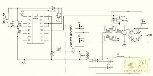
And let's make it clear that the block of life is strongly motivated and at one time vicious. Mi yogo is turned on, but the charging of the capacitors does not work, just burn the resistor on the charge and that's it. Bida, ale solution. The other contact group of the relay is normally closed, and if the input of 4 microcircuits is closed with a stabilizer of 5 volts for 14 nodes, then the pulse trivality will decrease to zero. The microcircuit will be switched off, the power keys will be closed, the input capacity will be charged, the relay will click, the charge of the capacitor C5 will turn on, the width of the pulses will rise to the working level, the block will be ready to work. If the voltage drops in the cell, a relay will be switched on, which will lead to the switching on of the control circuit. When the voltage is restored, the start-up process will be repeated again. I’ve learned to competently scribble, if I can see through it, I’ll be radium, be it some kind of respect.
Stabilization of the struma, it plays a bigger role here, if you want to be able to regulate it with a change resistor. Implemented through a struma transformer, to which the living block was adapted with a bipolar output, but not everything is simple there. The expansion of this transformer is even easier - the shunt with the support R Ohm is transferred to secondary winding from the number of turns N as opir Rnt = R * N ^ 2, it is possible to determine the voltage of the sp_v_dnoshnennia of the number of turns and the fall on the equivalent shunt, it can be greater than the lower voltage of the fall of the diode. The mode of stabilization of the stream will start again, if the voltage at the input of the operator tries to change the voltage at the input. Vikhodyachi z thogo rozrahunok. Primary winding - wire stretching through the ring. Varto vrahuvati, that the urvishche navantazhennya of the struma transformer can be brought before the appearance of great voltages on its output, taking sufficient for the breakdown of the pidsiluvach pardon.
Capacitors C4 C6 and resistors R10 R3 make a differential switch. For rahunok lansyuk R10 C6 and mirrored R3 C4 there is a tricurate decline in the amplitude-frequency characteristic of the sweet pardon. It looks like a full change in the width of the impulses in the fallow in the stream. From one side, do not reduce the speed zvorotny zv'azku, from the other side, to rob the system with a steady hand. Here, it’s safer to look at the frequency response below 0 decibels at a frequency of three times more than 1/5 of the shim frequency, such a catchy sound to finish the swede, at the sight of a turning sound from the output of the LC filter. The frequency on the cob is zruzu -3db is developed as F=1/2prRC de R=R10=R3; C=C6=C4 Vlasne stronger
The circuits are taken into account as the maximum possible voltage (dead hour is equal to zero) on the capacitor C4 to the voltage of the file generator inserted into the microcircuit and converted to decibels. Vono lifts the frequency response of a closed system uphill. It’s safe to say that our compensating lances give a drop of 20db per decade, starting at a frequency of 1/2pRC and knowing that it’s not easy to know the breakpoint of 0db, as it can be no more lower at a frequency of 1/5 of the operating frequency, then. Varto respect that the transformer is not winding with a large margin of tension, but the strum is not guilty of a particularly large one, otherwise it is impossible to put on high-frequency floorings at once, but a kiloampere jumps out there quickly. So it's not evil.
That's all for today, I'm sure the scheme will be correct. Її it is possible to adapt the power supply of the screwdriver, or to create a bipolar wind for the life of the power supply, so the self-possible battery charge in a stable jet. According to the latest connection tl494, it was found in the last part, in addition to it, only the soft start capacitor C5 and the relay contacts on the new one. Well i respectful respect- control of the voltage on the capacitors on the bridge by connecting the control circuit with the power in such a way that it is not allowed to eat the condenser, which is to be extinguished, using the bridge voltage. Possibly solution - half-wave vipryamlyach n_bito diode nap_vm_st or transformer in black.
ID: 1548
|
How do you like the article? |
TL494
More fate passed, as I seriously took up the topic of life blocks. Having read the wonderful books by Marty Brown "Dzherela Kharchuvannya" and Semyonov "Power Electronics". As a result, after impersonal pardons in circuits from the Internet, and for the rest of the hour, just a little more zhorstoke about my beloved TL494 microcircuit.
I love TL494 for its versatility, singsongly, there is no such block of life, which would be impossible to implement on it. In this view, I want to take a look at the implementation of a similar topology "napivmist". The control of transistors on the bridge becomes galvanically rozv'yazam, it takes a few elements, in principle it changes in the middle of the change. Irrespective of those who use impersonal bridge drivers, it’s better to write off as a transformer driver (GDT) early, this method is the most reliable. The bootstrap drivers vibrated, and I haven't seen the GDT vibrating axis yet. The driver transformer is the most important. pulse transformer, Rozrakhovuєtsya for the same formulas as a forceful vrakhovuychi scheme of rozgoduvannya. Often I'm looking for hard transistors in GDTs. Output microcircuits can see 200 milliamps of strum and in case of a well-informed driver it is even richer, especially blowing at a frequency of 100 kilohertz IRF740 and winding IRFP460. Let's look at the scheme of the driver:
T
qia scheme the GDT skin winding is switched on. On the right, in the fact that at the time of the dead hour, the primary winding of the transformer appears to be open, and the secondary is not energized, then through the winding itself the discharge of the shutters will go to the edge for a long time, the introduction of a resistor, which will close, will cause the shutter to charge quickly and have a lot of energy for free. The scheme of the little one was spared by tsikh nedolіkіv. The fade fronts on the real layout were 160ns rising and 120ns falling at the gate of the IRF740 transistor.

Similarly, transistors were motivated to add to the bridge in the GDT. The zastosuvannya rozgoduvannya by the bridge is connected with it, that before the activation of the trigger of life tl494 after reaching 7 volts, the output transistors of the microcircuit will be switched on, when the transformer is turned on, the push-pull will be short chirp. Mist works stably.
The diode seat VD6 directs the voltage from the primary winding and if it is necessary to shift the voltage, then turn it back into the capacitor C2. Vіdbuvaetsya tse through the appearance of the voltage of the revolving course, but the inductance of the transformer is not infinite.
The circuit can be live through a capacitor, which can be extinguished, at a time 400 volt k73-17 at 1.6 microfarads. diode kd522 or significantly shorter for 1n4148, it is possible to replace it with a larger voltage 1n4007. You can visit the entrance to 1n4007 or to win the preparations for kts407. On the board of the pardons of the kts407 yak VD6, it is unacceptable to put it in any case, this place is to blame for the viking on the high-frequency diodes. Transistor VT4 can run up to 2 watts of heat, but it plays a role for a short time, you can stop kt814. Other transistors kt361, moreover, it is not necessary to replace the low-frequency kt814. Set the tl494 generator to the frequency of 200 kilohertz, which means that in two-cycle mode, 100 kilohertz is taken. Motaёmo GDT on a ferite ring 1-2 centimeters in diameter. Provid 0.2-0.3mm. The turns can be a dozen times greater than the rozrahunkov value, which greatly improves the shape of the output signal. The more it is wound, the less it is necessary to drive the GDT with resistor R2. I wound 3 windings of 70 turns on coils with a diameter of 18mm. There is a dependency on the number of turns and an increase in the number of windings due to a tricot warehouse struma, it changes with an increase in windings, and an increase in windings simply changes in the third windfall. The fee is added, the prote is not compatible with the scheme, but the main blocks on it are plus the additions of the body of one power supply unit of the pardon and the last stabilizer for powering the transformer output. The payment of the vikonan for installation at the opening of the payment of the power unit.
One more charging attachment was selected for the circuit of the key stabilizer of the stream with a voltage control unit on the battery to ensure its activation after the charging is completed. To control the key transistor, the TL494 microcircuit (KIA491, K1114UE4) is widely expanded. Attachment ensures the regulation of the stream of charge in the ranges of 1 ... 6 A (10A max) and the output voltage of 2 ... 20 V.
The key transistor VT1, diode VD5 and power diodes VD1 - VD4 must be installed through mica gaskets on a hot radiator with an area of 200 ... 400 cm2. The most important element of the scheme is the L1 throttle. Vіd yakosі prepared to lay down the KKD scheme. As a core, it is possible to use a pulse transformer in the living block of TV sets 3USCT or similar. It is even more important that the magnetic conductor should have a gap of approximately 0.5...1.5 mm great strums. The number of turns to lay in a specific magnetic circuit and may be in the range of 15 ... 100 turns of a PEV-2 2.0 mm wire. Since the number of coils is transcendental, then when the circuit is operating in the nominal voltage mode, there will be a remarkably quiet whistling sound. As a rule, the whistling sound is only heard at medium streams, and at high tension, the inductance of the choke for the magnetization of the core falls and the whistle is attached. Yakschko whistle sound is prescribed with non-religious strips І with a deputy zb_lshenni stream Navalanthum Rіzko Zakyuyki Vikhіdniy Transistor, meaning the core of the Magnіtoprovide Sunday for Roboti on Obraniy frequency of the genesії - needless zb_lshiti Rack frequency Mіkrosemi pіdbor resistor R4 Abo C3 Capacitor ABO ABO. With presence power transistor p-n-p structures in the circuit can be twisted with power transistors structures n-p-n, as shown in the little one.
Like the VD5 diode in front of the L1 inductor, it is necessary to vicorate whether it is available diodes with a Schottky barrier, installed on the stream not less than 10A and a voltage of 50V, in the extreme case it is possible to vicorate mid-frequency diodes KD213, KD2997 or similar. For a vipryamlyach, you can vikoristovuvat whether it is a dim diode for 10A strum or a single place, for example KBPC3506, MP3508 or similar. Opir of the shunt in the scheme is necessary. The range of regulation of the output stream is to lie down in the sp_v_dnoshnennia of the supports of the resistors of the lantsyug of the 15th microcircuit. At the bottom of the diagram of the position of the engine of the change resistor, the regulation of the struma voltage on the output microcircuit 15 can be increased from the voltage on the shunt when passing through the new maximum struma. The replacement resistor R3 can be installed with a nominal support, or you can add a constant resistor R2 with it to remove the necessary voltage on the displayed microcircuit 15.
The replacement resistor for regulating the output voltage R9 can have a large nominal support of 2 ... 100 kOhm. By selection, the support of the resistor R10 is installed upper cordon output voltage. The lower boundary is dependent on the support of resistors R6 and R7, but it is not necessary to install less than 1V.
The microcircuit is installed on a small other board 45 x 40 mm, the grid of the circuit elements is installed on the base of the attachment and the radiator.

The wiring diagram for connecting a different board is shown below.
Variants of other boards at lay6

Thank you for the seals in the comments Demo

In the scheme of rewinding the power transformer TS180, but in the fallow, depending on the value of the required output voltage and the stream, the tension of the transformer can be changed. If there is sufficient output voltage of 15 and a stream of 6A, then a power transformer with a voltage of 100 W is sufficient. Radiator area can also be changed up to 100..200 cm2. Priest can vikoristovuvatsya like laboratory block zhivlennya z regulation obezhennyam vyhіdnogo struma. With the correct elements, the scheme is repaired again and will require only further construction.
Dzherelo: http://shemotekhnik.ru


