Zahist navantazhennya stabilizator naprugi postіyny strumu. Parametric voltage stabilizers. Rozrahunok of the simplest parametric stabilizer on a stabilitron
In order to cope with shifts in the mesh, you need a strum stabilizer. These extensions can be questioned for their characteristics, but they are tied with life jackets. Buy fit in the booth is not more powerful in terms of stabilization of the struma, but the control of the environment requires a stable voltage. Zavdyaki bezpereshkodnymi models from 'was able to take reliable information from their records.
How to improve the stabilizer?
The main element of the stabilizer is a transformer. If you look at a simple model, then there is a straight line. It connects with capacitors, as well as with resistors. In lancius, different types can be installed and the boundary line of stench can be seen differently. Also, the stabilizer has a capacitor.
Robotic principle
If the strum consumes a transformer, then the cutoff frequency changes. At the input, this parameter is in the region of 50 Hz. Zavdyaky peretvorennuyu struma cutoff frequency at the exit to become 30 Hz. High-voltage rectifiers evaluate the polarity of the voltage. Stabilization of the strum at the time of the winding of the condensers. Reduction of the shift code in the resistors. At the output, the voltage becomes constant again, and the transformer should be connected with a frequency of no more than 30 Hz.
Schematic diagram of the relay add-on
Strumu relay stabilizer (diagram shown below) includes compensation capacitors. Mostovі vypryamlyachі razі vikoristovuyutsya on the cob lanceug. Also, you should lie that the transistors in the stabilizers have two bets. One of them is installed in front of the condenser. Necessary for moving the cutoff frequency. In this direction, the voltage is out fast strumu perebuvatime on equal 5 A. Schob nominal opir vitrimuvalosya, vikoristovuyutsya resistors. For the simplest models of power and two-channel elements. The process of transformation at times will be long, the proteo coefficient of expansion will be insignificant.
Attachment to stabilizer LM317
As is obvious from the name, the main element of the LM317 (stromu stabilizer) is a triac. I'll give the wine a colossal increase in the boundary pressure. At the exit, this indicator is oscillating in the region of 12 V. Zovnishniy opir is seen by the system at 3 ohms. For a high coefficient of smoothing, there are rich channel capacitors. For high-voltage attachments, transistors of a more open-type type are used. Changing their positions in such a situation is controlled for the change of the nominal stream at the exit.
Differential opir LM317 (stabilizer struma) vitrimu 5 Ohm. For vimiruvalnyh priladіv tsey pokaznik can become 6 ohms. The non-robust mode of the inductor is secured for the chamber of the hard-wired transformer. Restore Windows standard scheme behind the straightener. Diode bridges for low-frequency devices are rarely used. If you look at the receivers for 12, then for them the power resistors of the ballast type. This is necessary in order to reduce the colic of the lancer.
High frequency models
The high-frequency strum stabilizer based on the KK20 transistors is subjected to a quick transformation process. It is necessary to change the polarity at the exit. Frequency-setting capacitors are installed in lances in pairs. The front of impulses in such a situation is not guilty of overshooting 2 μs. In the other case, the struma stabilizer on the KK20 transistors is checked for significant dynamic losses. The number of resistors in the lances can be used for additional support. The standard scheme їх has transferred less than three units. To change the heat inputs, replace the capacitors. Shvidk_sn_ characteristics of the key transistor lie only in the value of the dilnik.
Pulse width stabilizers
The pulse-width stabilizer of the struma is surprised by the great values of the inductance of the inductor. Vіdbuvaєtsya for the rahunok shvidkoї change dilnik. Also, make sure that the resistors in this circuit are dual-channel. Strum the stench of the building to pass in different directions. Capacitors in the system are victorious. For the light of which, the boundary opir at the exit is seen only at a level of 4 ohms. In their own hands, the maximum voltage stabilizers can trim 3 A.
For vimiryuvalnyh outbuildings, such models are rarely finished. Dzherela zhivlennya in this situation, the limiting voltage is due to the mother no more than 5 V. In this rank, the coefficient of rozsiyuvannya is changed in the boundaries of the norm. Shvidk_sn_ characteristics of the key transistor in stabilizers this type not too high. It is connected with the low building resistance of the resistor blocking the strum from the vipryamlyach. As a result, high-amplitude transitions are brought up to significant heat losses. Decrease the impulses at different times are switched on and off with an additional decrease in the neutralization of the power of the transformer.
The process of transformation is only occupied by a ballast resistor, which is roztashovuetsya behind the rectifier bridge. Napіvprovіdnikovі diodes at vicorist stabilizers rarely. The need for such inputs falls through those that the front of the impulses near the lancet, sound, climbs at 1 μs. Through war, dynamic losses in transistors are fatal.
Scheme of resonant extensions
The resonant stabilizer of the struma (the circuit is shown below) includes small capacitors and resistors with a small support. Transformers at the same time are indistinguishable part of subsidiaries. To increase the coeficient of the brown divinity, there are impersonal defenders. Dynamic characteristics of resistors depending on the growth. Low frequency transistors mounted immediately behind the straighteners. For good conductivity of the stream, the capacitors should be used at different frequencies.
Stabilizer
Strum stabilizer of the same type with an invisible part of the dzherel zhivlennya potuzhnistyu up to 15 V. Zovnishniy opir pristraymaetsya up to 4 ohms. The voltage of the changeable stream at the entrance to the middle one should be 13 V. In this type, the smoothing coefficient is controlled for the voltage of the critical capacitor type. Riven ripple at the output to lie in the circuit of the resistors. The threshold voltage of the stabilizer of the struma can be built-up vitrimuvat 5 A.
In times, the parameter of the differential support is to blame for the value of 5 ohms. The maximum allowable potency of the rose is 2 watts. Why talk about those who are stabilizers snake struma may have problems with the front of impulses. Change their colivanna in different buildings, there are no more bridges and straighteners. In case of obov'yazkovo, the value of the dilnik is guaranteed. To reduce heat losses, stabilizers are installed at the stabilizers.
Model for light diodes
For the regulation of light of the great tension, the stabilizer of the struma is not to blame for the mother. At this point, the task is to ensure that the threshold of expansion is minimized as much as possible. Zrobiti stabilizator strumu for svitlodiodіv mozhe dekіlkom ways. Nasampered, the models are getting turned around. As a result, the cutoff frequency of all stages is selected at 4 Hz. In this case, it gives a significant increase in the productivity of the stabilizer.
Another way is based on vikoristan subsidiaries. In such a situation, everything is tied to the neutralization of the snake strum. To change the dynamic inputs, the transistors in the circuit are high-voltage. Let's get into the habit of building elements of open-type capacitors. For the most wide code transformers, key resistors are used. In the scheme, the stench is standardly installed behind the vibrating bridge.
Stabilizer with regulator
Regulation stabilizer of the stream of requests from the industrial sphere. With the help of the help of the koristuvach, you can carry out the installation of the annex. Dodatkovo a lot of models for insurance coverage remote control. With this method, controllers are mounted at the stabilizers. The limiting voltage of the changeable struma is less than 12 V. The stabilization parameter is more likely to become less than 14 watts.
The indicator of the boundary pressure to fall on the switch-only in the frequency of the device. To change the smoothing coefficient regulation stabilizer strum vikoristovuє єmnіsnі condensers. The maximum strum system is supported only on the level of 4 A. In its own right, the indicator of the differential support is allowed on the level of 6 Ohm. It's all worth talking about the good productivity of stabilizers. Prote pouzhnіst rozsіyuvannya can even be irritated. It is also important to know that the non-robust mode of the inductor is protected by the transformer.
The voltage is applied to the primary winding through the cathode. Blocking the struma at the exit to lie down is less than a type of condenser. To stabilize the process, the guards do not ring out. The system's code is secured with additional impulse drops. Shvidky process of transforming the struma of the lanceg to bring it down to the front. The transistors in the circuit are switched on and off of the key type.
Post-strum stabilizers
The stabilizer of the post-strum is based on the principle of sub-wind integration. Reworking in all models is required for the whole process. To improve the dynamic characteristics of stabilizers, two-channel transistors are used. To minimize the heat input, the capacity of the capacitors can be significant. The exact rozrahunok of the value allows the increase of the indicator of the straightening. When the output voltage of the steady stream is 12 A, the maximum value can become 5 V. In this case, the operating frequency will be adjusted to 30 Hz.
Threshold voltage to lie in blocking the signal of the transformer. The front of impulses at times is not guilty of overshooting 2 μs. The number of key transistors is only needed after the transformation of the stream. The diodes of this circuit can be vicorated exclusively of the conductor type. Ballast resistors bring the strum stabilizer up to significant thermal losses. As a result, the coefficient of expansion is even older. As a result - the amplitude of the colivan increases, the process of inductance does not become.
Parallel parametric stabilizer, subsequent stabilizer on a bipolar transistor. Practical razrahunki.
Good day, Radioamatori's champs!
Today on the site "", at the distribution "", we continue to look at the article "". I’m guessing that the past time, while watching the diagram of the life of the radio amateur extensions, we stumbled on the recognition of that rozrahunka filter, which smooths out:
Today, let's look at the remaining element - the voltage stabilizer.
Voltage stabilizer - converting electric energy, which allows you to take the output voltage, which is in the tasks between the input voltages and the input voltage support
Today we will look at two of the simplest voltage stabilizers:
- ;
– .
Parallel parametric voltage stabilizer on a stabilitron
Napіvprovіdnikovy stabilіtron - (another name - Zener diode) of appointments for stabilization of the constant voltage of the living life. IN the simplest scheme linear parametric stabilizer Vіn acts simultaneously as a support voltage, and as a power regulating element. In folded schemes, the role of the support voltage is assigned to it.
One s beautiful views that sign of the zener diode:
How to work stabilitron
The voltage on the zener diode (on the input of the diode) is applied at the reverse polarity (the anode is connected with a minus, and the cathode is connected with a plus) Uobr). With such a connection through the zener diode, the flow return strum – Iarr.
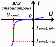
When the voltage is increased, the turning strum grows even more correctly (in the diagram, may be parallel to the axis Uobr), but with singing pressure Uobr the transition of the stabilitron breaks through (although the stabilitron collapse is not observed at the moment) and through the new one begins to go through a turning strum of significantly greater significance. At this moment, the current-voltage characteristic of the zener diode ( VAC) sharply go down (mayzhe parallel to the axis Iarr) - enter the stabilization mode, the main parameters of this - the stabilization voltage is minimal ( Ust min) and strum stabilization minimal ( Іst min).
With a little increase Uobr I-V characteristic of the stabilitron again changes its direct current - the stabilization mode ends, the main parameters of this - the maximum stabilization voltage ( Ust max) that strum stabilization maximum ( Ist max). From this moment, the zener diode loses its power, begins to grow, which can lead to a thermal breakdown of the transition of the zener diode and, as a rule, to the yogo exit from the fret.
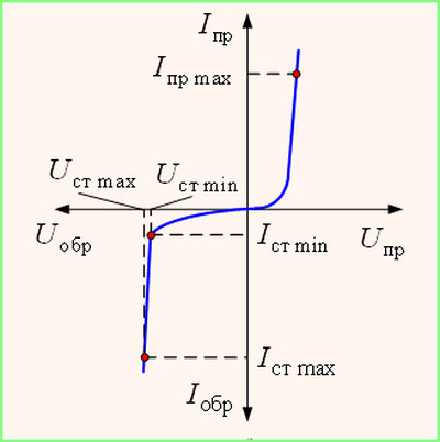
The stabilization mode of the zener diode can be in wide ranges, so in the documentation for the stabilitron it is indicated the permissible minimum and maximum values of the strum ( Іst minі Ist max) and stabilization voltage ( Ust minі Ust max). Use the middle of these ranges to lie selected by the virobnik nominal meaning – Іstі Ust. Nominal strum stabilization sound is set by vibrators at the level of 25-35% of the maximum, and the nominal value of the stabilization voltage is the average of the maximum and minimum.
For the butt, you can speed up the program “ “ and on the vlasnі ochі marvel at the characteristics to be induced in the drivers of the stabilitronіv:
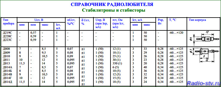
For example stabilitron D814G:
- rated stabilization jet (Іst) = 5 mA;
– Rated voltage stabilization (Ust) \u003d (vіd 10 to 12 volts) \u003d 11 volts;
- Maximum stabilization stream (Ist max) = 29 mA.
These data will be necessary for the installation of the simplest voltage stabilizer.
If you could not know the needs of our native, radyansky, stabilitron, then you can win, for example, a program, choose a bourgeois analogue for the required parameters:
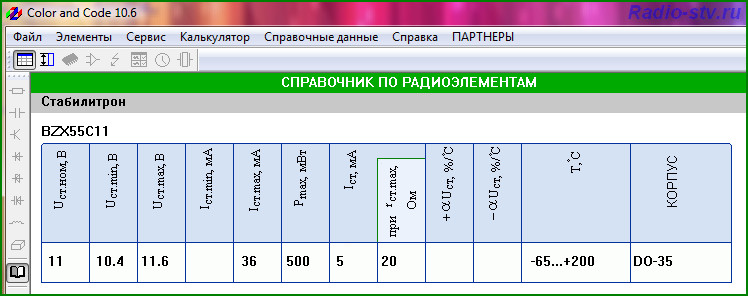
Like a bachite, the stabilitron D814G can be easily replaced by an analogue - BZX55C11
Well, now let's take a look parallel parametric voltage stabilizer on a stabilitron.
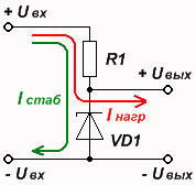
Parallel parametric voltage stabilizer on a stabilitron zastosovuєtsya in low-current outbuildings (kіlka miliamper) R– ballast resistor and zener diode VD- which wins the role of another resistor) an unstable voltage is applied to the input of which, and the output voltage is taken from the lower shoulder of the dilnik. When the input voltage is increased (reduced), the internal support of the zener diode changes (increases), which allows to reduce the output voltage at a given level. On the ballast resistor, the difference between the input voltage and the voltage stabilization of the zener diode drops.
Let's look at the scheme of this (simplest) voltage stabilizer:
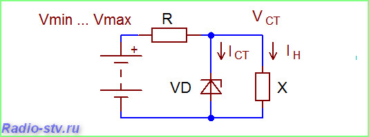
For normal robotic scheme the strum through the stabilitron is guilty in the kіlka of times (3-10 times) to change the strum in the stabilized direction. Practically, the oscills of the rated strum of stabilization of the zener diode are a few times less than the maximum, then it is allowed during re-roofing, if the strum of the voltage is not guilty of exceeding the rated strum of the stabilization.
For example: strum of adjustments to vanishings to become 10 mA, it means that we need to choose such a stabilitron, so that its nominal stabilization strum is not less than 10 mA (better zvichayno, as it will be larger).
Rozrahunok of a parallel parametric voltage stabilizer on a stabilitron
Given:
Uin- Input voltage = 15 volts
Uvix- Output voltage (stabilization voltage) = 11 volts
Rozrahunok:
1.
For a good reason, we’ll make it better, we’ll decide what stabilitron D814G is suitable for our purposes:
Ust(10-12v) = 11 volts
Ist max= 29 mA
Іst nominal = 5 mA
Vihodyachi zі what was said above, vyznaєmosya, that the strum of ambition is not guilty of revisiting Іst nominal - 5 mA
2.
We can see the voltage drop on the ballast resistor (R) as a difference between the input and output stabilized voltages:
Upad = Uin - Uin= 15-11 = 4 volts
3.
Vikoristovuyuchi Ohm's law, denoting the nominal value of the ballast support R, dilating the voltage drop
R= Drop/Ist= 4 / 0.005 = 800 ohms
Shards of resistors with a nominal value of 800 Ohm are not available, we take the nearest higher nominal value - R = 1000 Ohm = 1 kOhm
4.
We can see the tension of the ballast resistor R:
Pres = Upad * Ist\u003d 4 * 0.005 \u003d 0.02 watts
Shards through the resistor flow like a stabilizing strum of a zener diode and a strum of adjustments to the voltages, then the value of the minimum is greater:
Pres\u003d 0.004 * 2 \u003d 0.008 watts, which corresponds to the nearest nominal value \u003d 0.125 watts.
Well work, because you did not know the stabilizer with the necessary voltage stabilization.
You can get stuck in this vipadka the last build of stabilitrons. For example, if we need two stabilitrons D814G in series, then the stabilization voltage of the warehouse is 22 volts (11 + 11). If we use D814G and D810, then we take a stabilization voltage of 20 volts (11 + 10).
It is allowed to be the number of the last order of the stabilizer in one series (as in the butt - D8 **).
Last day Stabilizers of different series are allowed only in that case, as the working streaks of the last lancet fit into the passport range of streaks in the stabilization of the skin vicarious series.
What is the work, like in the case of the induced higher butt, the strum of ambition is to become, for example, not 5 but 25 mA?
It’s possible, obviously, everything is so redundant, since the maximum stabilization stream (Ist max) D814G is more than 29 mA, it’s only possible to overshoot the tension of the ballast resistor. But in any case, the stabilitron is practicable on the border of its possibilities and you will not have any guarantees that you will not get out of tune.
And what about the robit, how to set the strum of ambition, for example, 50 mA?
Post-voltage stabilizer on bipolar transistor
Post-voltage stabilizer on bipolar transistor- ce, in fact, a parallel parametric stabilizer on a stabilitron, connections to the input of the emitter repeater.
The voltage drop is less for the voltage of the stabilizer of the stabilitron for the voltage drop on the base-emitter junction of the transistor (for silicon transistors - about 0.6 volts, for germanium - about 0.25 volts), which needs to be reversed when choosing a stabilizer.
Emmіterny repeater (vin same - pіdsiluvach strum) allows to increase the maximum strum of the voltage stabilizer is equal to the parallel parametric stabilizer on the stabilitron β (h 21e) times (de β (h21e)- Strength coefficient for the stream of this transistor, take the smallest value).
Scheme of a post-stabilizer on a bipolar transistor :
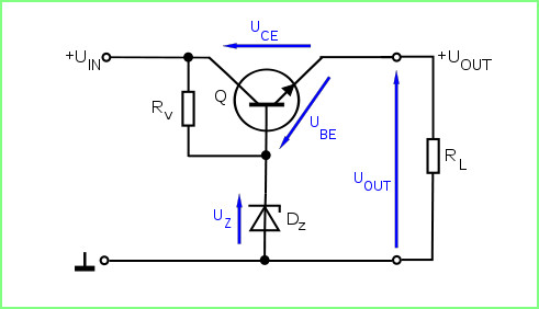
So, as a whole stabilizer is composed of two parts - reference voltage(in the same parallel parametric stabilizer on the stabilizer) and pіdsilyuvacha struma on transistors (in the same emmitter repeater), then such a stabilizer is fired similarly to the induced butt.
Single opinion:
- For example, we need to take a stream of 50 mA, then select a transistor with a gain coefficient β (h 21e) not less than 10 ( β (h 21e)\u003d Іvantage / Ist \u003d 50 / 5 \u003d 10
- The tension of the ballast resistor is calculated according to the formula: Рres = Upad * (Ist + Iadvantage)
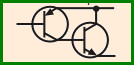
Strum input can be increased in a few times, so you can put a circuit with a folded transistor (two transistors connected behind the Darlington or Shikla circuit):
 Axis, principles, and everything.
Living block "Don't be simpler". Part of a friend
Yeah, zaishov? What, tsіkavіst tormented? Ale, I'm already radium. No true. Cheer up better, at once, and at once, work out simple tricks, like you need, to bungle a block of life, which we have already built in the first part of the article. I would like to say that these rozrahunki can become in good time and in more folding schemes.
Also, our living block is composed of two main nodes - the straightener, which is composed of a transformer, diodes, which are rectified, and a capacitor and a stabilizer, which is composed of the other. How to help the Indians, maybe, maybe, from the end, and rozrahuyemo a stabilizer on the back.
Stabilizer
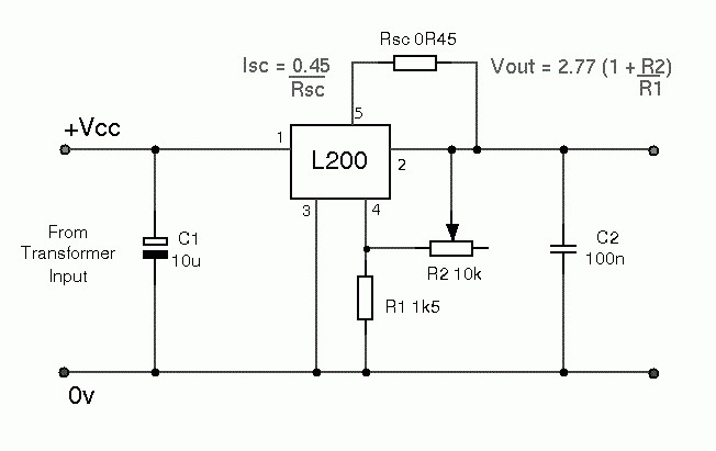
The scheme of the stabilizer is shown as a small picture.
Tse so ranks parametric stabilizer. Folded wine from two parts:
1 - the stabilizer itself on the stabilizer D with a ballast resistor Rb
2 - emіterny repeater on transistors VT.
Behind the clock, so that the voltage was drained, as we need, to stitch the stabilizer, and the repeater allows the switch push harder to the stabilizer. Vin plays the role of a nibi pіdsilyuvacha, or, as a rule, always - a helper.
The two main parameters of our live block are the output voltage and the maximum power stream. Let's name them:
Uvix- tse voltage
і
Imax- Tse strum.
For the block of life, which was used in the last part, Uvih = 14 Volts, and Imax = 1 Ampere.
It is necessary for us to calculate the return, as the voltage Uvh mi is due to the stabilizer, so that at the exit we take the necessary Uvh.
The voltage depends on the formula:
Uin = Uin + 3
Did you get the number 3? This is the voltage drop at the collector-emitter transition of the transistor VT. In this rank, for the work of our stabilizer, at least 17 volts are due to the yoga input.
Transistor
Significantly, what kind of transistor we need VT. For whom we need to signify, as the intensity of the wines rose.
Pmax=1.3(Uin-Uout)Imax
Here you need to call for a moment. For the rozrahunka, we took the maximum output voltage for the life block. Prote, at whom you have a rose, you need to take the minimum voltage, as you can see the BP. And it’s going to be 1.5 volts for our vipad. Even if it doesn’t work, the transistor can be covered with the middle pelvis, the shards of maximum tension will be incorrectly protected.
See for yourself:
If we take Uout \u003d 14 volts, then we take Pmax = 1.3 * (17-14) * 1 = 3.9 W.
How can we accept Uout \u003d 1.5 volts, then Pmax = 1.3 * (17-1.5) * 1 = 20.15 W
Tobto, yakbi did not lie to him, then it would be better if the rozrahun’s tightness was five times less than real. Zrozumіlo, transistors would not be worth it.
Well, from now let's go to the dovіdnik and choose your own transistor.
Crimson choyno otrimanoї natuzhnostі, treba vrahuvati, scho boundary voltage between the emitter and the collector can be more than Uin, and the maximum stream of the collector is to blame but more than Imax. I selected KT817 - a decent transistor.
Important the stabilizer itself.
On the other hand, the maximum strum of the base of the freshly selected transistor is significant (but you think? Our light has the most - navit base of transistors).
Ib max \u003d Imax / h21E min
h21E min- the minimum coefficient of transmission to the stream of the transistor and is taken from the driver. Well, I have more than one number written in my day - 25, with it I’m happy, but what else is left over?
Ib max \u003d 1/25 \u003d 0.04 A (or 40 mA). Chimalo.
Well, let's now shukatimemo stabilitron.
Shukati yoga is required for two parameters - tension stabilization and struma stabilization.
The stabilization voltage can be equal to the maximum output voltage of the life block, that is 14 volts, and the strum is less than 40 mA, that is, that which we praised.
Climbed again until late.
By pressure, we are afraid to walk a stabilitron D814D, Until then, I have a wine under my hand. Ale strum stabilization ... 5 mA is no good for us. What is working? We change the strum of the base of the output transistor. And for which one dodamo to the circuit, there is one transistor. We look at the little ones. We added transistor VT2 to the circuit. This operation allows us to reduce the voltage on the zener diode in h21E times. h21E, ozumіlo, of that transistor, which was added to the circuit. Without thinking too much, I took the KT315 baffle from the buy. Yogo minimum h21Е dorivnyuє 30, so we can change the strum to 40/30 = 1.33mA what do we need to do.
Now it’s important to check and tighten the ballast resistor Rb.
Rb = (Uin-Ust) / (Ib max + Ist min)
de Ust - stabilization voltage of the zener diode,
Ist min - stabilization stream of the zener diode.
Rb \u003d (17-14) / ((1.33 +5) / 1000) \u003d 470 Ohm.
Now the value of the resistor value is significant
Prb \u003d (Uin-Ust) 2 / Rb.
Prb \u003d (17-14) 2/470 \u003d 0.02 W.
Vlasne, that's all. In this order, from the output data - the output voltage and stream, we took away all the elements of the circuit and the input voltage, as it may be applied to the stabilizer.
Prote does not relax - they are checking on us. Already rahuvati so rahuvati, I am so impressed (pun intended).
Otzhe, we marvel at the scheme of the vipryamlyach.
Well, everything is simpler than that on the fingers. As far as we know, the voltage required to supply the stabilizer is 17 volts, we calculate the voltage on the secondary winding of the transformer. For whom pіdemo, yak and on the cob - from the tail. Later, after the filter capacitor, we are responsible for a voltage of 17 volts.
Vrahovyuchi those that the filter capacitor zbіlshuє vpryamlenu narug in 1.41 times, otrimuєmo, scho after the vіslаlyаuchoy bridge we can viiy 17/1.41 = 12 volts.
Now it’s safe that we use close to 1.5-2 volts on the vibrating bridge, also, the voltage on the secondary winding can be 12 + 2 = 14 volts. As long as it can be so that such a transformer is not found, it’s not scary - in this case, you can put a transformer with a voltage on the secondary winding of 13 to 16 volts.
Cf = 3200In / Un Kn
de In - the maximum strum of interest,
Un - voltage on the tension,
Kn - ripple coefficient.
To our liking
In \u003d 1 Ampere,
Un=17 volts,
Kn = 0.01.
Cph \u003d 3200 * 1 / 17 * 0.01 \u003d 18823.
However, shards behind a vibrating voltage stabilizer, we can change the rozrahunkovu capacity at 5 ... 10 times. So 2000 microfarads will be enough.
It was left to choose vibrating diodes and a diodny place.
For which we need to know two main parameters - the maximum strum that flows through one diode and the maximum turning voltage, just through one diode.
The required maximum return voltage is taken into account in this way
Uobr max \u003d 2Un, then Uobr max \u003d 2 * 17 \u003d 34 Volts.
And the maximum strum, for one diode, is due to the larger or larger strum of the energy block. Well, for the other folding in the dovіdniki, indicate the highest maximum strum, which can pass through the folding.
Well, from the beginning and everything about straighteners and parametric stabilizers.
In front of us, we have a stabilizer for the most advanced ones - on an integrated microcircuit and a stabilizer for the most advanced ones - a compensatory stabilizer.
ID: 667
|
How do you like the article? |
Napіvprovіdnikovy prilad, about which it may be, appointments for stabilizing the strum on the necessary level, may be low varіst and gives the possibility of asking for the development of schemes of rich electronic devices. I'll try to fill in a few pieces of information about simple circuitry solutions for stabilizers of a post-strum.
Trochy theory
Ideally, the strum could be surrounded by an infinitely great EPC and an infinitely great internal support, which allows you to take the necessary strum in the lance, an independent view of the support of the advancement.
Looking at the theoretical allowances for how the parameters of the strum dzherel help to understand the definition of the ideal dzherel strum. Strum, creating an ideal strum dzherel, becomes permanent when changing the support of the tension in the air short hum to inexcusability. To adjust the magnitude of the strum, the constant value of the EPC changes as a value not equal to zero to inconsistency. Power dzherela strumu, which allows you to take a stable value of the strum: when you change the support of the pressure, the EPC changes the strumu in such a rank that the meaning of the struma becomes permanent.
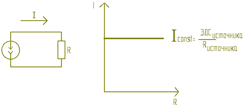
Really dzherela strumu podtrimuyut strum on the necessary level of the surroundings, the range of voltage, created on the edge of the edge of the edge of the tension. Ideally, it is possible to look at the strum, but in reality, the strum can be considered as a zero support for the tension. The strumu stuttering mode is not a fault, but the strumu stuttering function, which is important to implement, is one of the operating modes, in which you can safely switch to the device in case of a strumming output stuttering and switch to the operating mode with a voltage support greater than zero.
Really zherelo struma vikoristovuetsya at once іz zherelom naprugi. Merezha 220 volts 50 Hz, laboratory block life, battery, gasoline generator, a sony battery - dzherela naprugi, scho supply electricity spozhivachevi. Consistently with one of them, the strumu stabilizer is switched on. When such an attachment is taken, it is like a jerelo strum.
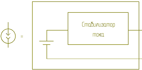
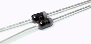
The simplest strum stabilizer is a dual component that surrounds the strum, which flows through it, the size and accuracy of which are similar to those of the virobnik company. Such a napіvprovіdnikovy prilad zdebіlhogo maє corps, scho guessing the diode of small tension. The origins of the zvnіshnіy similarity and the obviousness of the whole two visnovkіv components of this class are often guessed in the literature as dione stabilizers of the strum. The internal scheme does not avenge the diodes, such a name has become more familiar than the sound of similarity.
Apply two stabilizers to the strum
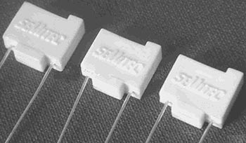
Diode stabilizers of the struma are released by the bagatma sipifiers.
|
1N5296 Strum stabilization 0.91mA ± 10% |
|
|
E-103 Strum stabilization 10 mA ± 10% |
|
|
L-2227 Strum stabilization 25 mA ± 10% |
|

From theory to practice
The installation of diode stabilizers in the stream will simplify electrical circuits and reduce the variability of accessories. The choice of other stabilizers of the strum was added not only by its simplicity, but also by the improvement of the stability of the robots, which are being developed. One conduit of the same class is fallow type, ensuring the stabilization of the struma at a level of 0.22 to 30 mA. The names of these heating fittings according to GOST did not know that circuit designation. In the schemes of the article, it happened to zastosuvat the value of the great diode.
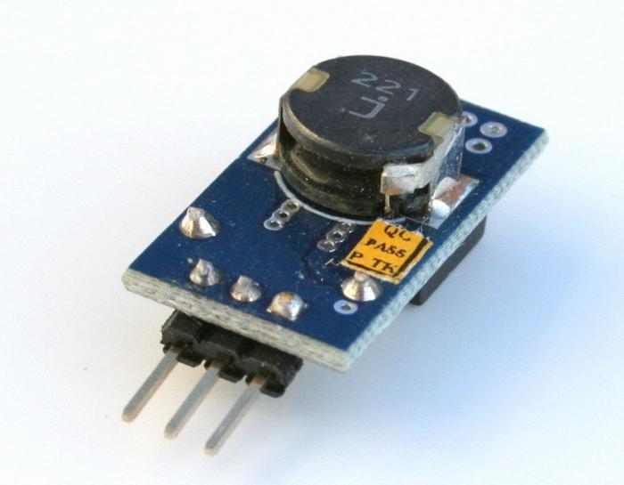
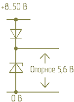
With the inclusion of a light-emitting diode in the lancet, the diode stabilizer ensures the required mode and operation. One of the features of the diode stabilizer strum - a robot in the range of voltage from 1.8 to 100 volts, which allows you to protect the light diode in the output from the fret with the influx of pulsed and triple voltage changes. Yaskravist and vіdtinok svіtіnnya svіtlodіod lie in the struma that flows through. One single struma stabilizer can ensure the operation of a number of successively increased light diodes, as shown in the diagram.
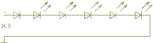
Qiu scheme is easy to recreate fallow in light of light and voltage of life. One or more parallel inclusions of one of the stabilizers of the stream into the lance of light diodes are to set the stream of light diodes, and a number of light diodes are to be deposited in the range of changing the voltage of life.
For the help of one dzherel strumu, you can induce an indicator illuminating fixture, appointments for living in the form of a constant voltage Zavdyaki living with a stable strum dzherelo light mother constant lightness of the light when the voltage of living is broken.
The change of the resistor in the ledge of the light diode of the indicator of the voltage of the life of the engine of the constant stream of the verst of the Sverdlovka of the other boards led to a quick exit from the fret of the light diode. Zastosuvannya diode stabilizer strum allowed to take away the superior work of the indicator. Diode stabilizers and struma are allowed to be switched on in parallel. The required mode of living can be eliminated by changing the type or including, in parallel, the required number of devices.
When the light-emitting diode of the optocoupler is alive through the pulsation resistor, the voltages of the live circuit are brought to the level of brightness, which are superimposed on the front of the rectilinear pulse. Zastosuvannya diode stabilizer strum lansyuga zhivlennya svetlodioda, scho to enter the warehouse of the optocoupler, allowing to reduce the occurrence of a digital signal that is transmitted through the optocoupler and zbіshiti nadіinіst channel information.
Zastosuvannya diode stabilizer strum, which sets the mode of operation of the zener diode, allows you to expand a simple core of the reference voltage. When changing the live stream by 10 VDC, the voltage at the zener diode changes by 0.2 VDC, and since the stream is stable, the value of the reference voltage is stable when other factors are changed.
Having injected the pulsating voltage of life into the outer reference voltage, the voltage changes by 100 decibels.
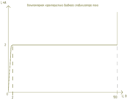
Internal scheme
The current-voltage characteristic helps to understand the work of the diode strumu stabilizer. The stabilization mode is due to the overvoltage on the windings, the attachment is close to two volts. At voltages above 100 volts, there is a breakdown. The real stabilization strum can be adjusted to the nominal strum up to ten hundredths. When changing the voltage from 2 to 100 volts, the stabilization jet changes by 5 watts. Diode stabilizers of the strum, as if they are released by deaky virobniks, change the strum of stabilization when the voltage is changed up to 20 Vdsotkiv. If the strum is stabilized, then there is more respite from the increased voltage. Parallel inclusion of five accessories, rozrohovanih 2 miliamps per jet, allows you to take more high parameters, lower one per 10 miliamperes. So, as the minimum voltage of the stabilization of the struma changes, the range of the voltage in the stabilizer increases.
The basis of the scheme of the diode stabilizer Strumu is a polovy transistor p-n transition ohm. The voltage of the shutter-turn determines the jet to the drain. When the voltage of the gate-coil is equal to zero, the strum through the transistor reaches the cob stream to the drain, which flows when the pressure is between the drain and the coil of a larger voltage. Therefore, for a normal robotic diode stabilizer, the current of the voltage applied to the visnovkiv is due to the greater value for the deake, from 1 to 3 volts.
The polovy transistor may have a large cob stream flow to the drain, so that the amount of transfer is not possible. Cheap diode stabilizers strumu є vіdіbranі on the strumu polovі transistors, which have a shutter with a coil.
When changing the polarity of the voltage, the diode stabilizer of the struma is converted to the primal diode. Tsya vlastіst vіst is swindled by tim, scho p-n transition field effect transistor there is a shift in the direct line and the jet flow along the lantern of the shutter-stik. The maximum return strum of any of the strum stabilizers can reach 100 mA.
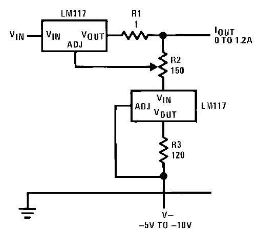
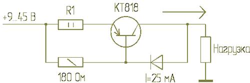
Dzherelo strumu 0.5A and more
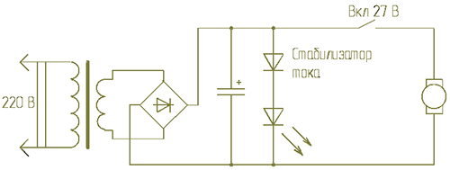
For stabilization of strums with a power of 0.5-5 amperes and more, a circuit is installed, the head element is hard transistor. The diode stabilizer struma stabilizes the voltage on the resistor 180 Ohm and on the basis of the KT818 transistor. Resistor R1 change from 0.2 to 10 ohms For an additional circuit, you can remove the strum, surrounding the transistor with the maximum strum or the maximum life strum. Zastosuvannya diode stabilizer strumu z most possible nominal strum stabilizatsii improves the stability of the output stream of the circuit, but at the same time it is impossible to forget about the minimum possible voltage of the robotic diode stabilizer of the stream. Changing the resistor R1 by 1-2 ohms significantly changes the value of the output stream of the circuit. This resistor is to blame for the mother's great intensification of the rise of heat, changing the support through heating will bring it to the exhalation of the outlet stream from the given value. Resistor R1 is shorter than the choice of a large number of parallel high-pressure resistors. Resistors, fixed at the circuit, due to the mother of the minimum support when changing the temperature. When prompted by a regulated dzherel stable struma or for fine tuning of the output stream, the 180 ohm resistor can be replaced with a different one. To improve the stability of the struma, the KT818 transistor is powered by another low-pressure transistor. Transistors follow the folded transistor circuit. When vikoristanny folded transistor minimal voltage stabilization zbіlshuєtsya.
This circuit can be used for living solenoids, electromagnets, windings of small motors, for galvanizing, for charging batteries and for other purposes. The transistor is obov'yazkovo installed on the radiator. The design of the fitting is responsible for ensuring good thermal insulation.
For deykih electric lancers and schemes of the cycle of vistachaє zvichayny block of life, but can not stabilize. Dzherela struma of this type sound is composed of a step-down transformer, a diode vibrating bridge and a filtering capacitor. Vihіdna napruga block zhivlennya lie down in іd kіlkostі vіtkіv secondary winding on a step-down transformer. Ale yak vіdomo shear stress 220 volts is not stable. It can swell at certain boundaries (200-235 volts). In this case, the voltage on the transformer is also “floatable” (at the place it is permissible to have 12 volts, it will be 10-14, or close to that).
Electrical engineering, as it is especially not suitable for small changes in the life-giving constant voltage, can be treated with such an axis simple block eating. Ale, sensitive electronics can’t stand it anymore, you can get out of tune in any way. So, blame the need for an additional scheme for stabilizing the constant output voltage. At this article, I will build an electrical circuit to complete a simple stabilizer of a constant voltage, which may be a stabilizer and a transistor. The zener diode itself acts as a supporting element, which is responsible for stabilizing the voltage of the life block.
Now let's move on to a straight-forward discussion electrical circuits a simple constant voltage stabilizer. Also, for example, we have a step-down transformer with a variable voltage of 12 volts. We supply 12 volts to the input of our circuit, and to the diode place and the filtering capacitor. Diodniy vipryamlyach VD1 from zminny struma to rob postyyny (alae stribkopodіbny). It is also responsible for the maximum strength of the strum (with a small margin of approximately 25%), which can be seen as a block of life. Well, and the voltage of їх (reverse) may not be lower than the output.
The filtering capacitor C1 smooths out the voltage strips, making the shape of the constant voltage more even (though not ideal). Yogo єmnіst can be buti from 1000 microfarads to 10000 microfarads. Tension, also more for the weekend. Fuck, what is such an axis effect. changing voltage after the diode bridge and the filter capacitor, the electricity is increased by approximately 18%. Also, in the result, we take not 12 volts at the output, but 14.5.
 Now part of the constant voltage stabilizer is being repaired. The main functional element is the zener diode itself. I’m guessing that stabilitrons can build up at certain boundaries to stably trim on themselves a constant constant voltage (stabilization voltage) when turned on. When applying a voltage of 0 to the stabilizer voltage, it will simply increase (at the ends of the stabilitron). Diyshovshi up to the level of stabilization, the voltage will be left unchanged (with insignificant increases), and the strength of the struma, which flows through the new one, will grow more and more.
In our scheme of a simple stabilizer, which is responsible for the output of 12 volts, the VD2 stabilizer voltage is 12.6 (we put a stabilizer for 13 volts, for example, D814D). Why 12.6 volts? That's why 0.6 volts settle on the transistor junction emitter-base. And at the output of the wire is exactly 12 volts. Well, if we put the zener diode at 13 volts, then the output of the PSU will be 12.4 V.
 The VD2 stabilitron (which creates the space of the reference constant voltage) will require an intermediate struma, which will protect it from overheating. In the diagram, the role is played by the resistor R1. As you can see, the connections are in series with the zener diode VD2. One more filtering capacitor electrolit C2 should be parallel to the zener diode. Yogo zavdannya also smooth out excess voltage pulsations. You can do without it, but still it will be better with him!
Dali on the circuit is a bipolar transistor VT1, which is connected behind the circuit by a hot collector. Guessing, wiring diagrams bipolar transistors behind the type of a hot collector (it is also called a semi-repeated collector) are characterized by the fact that the stench significantly strengthens the strength of the stream, but if there is no strength in the pressure (to wind it up a little less than the input, itself by 0.6 volts). Also, at the output of the transistor, we take that constant voltage, as it is at the same input (and the voltage of the reference zener diode itself, which is 13 volts). If the shards of the emіterny transition are on their own 0.6 volts, then the output of the transistor will no longer be 13, but 12.4 volts.
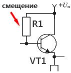 It’s the fault of the nobility that the transistor started to turn off (to pass through itself a keratin stream along the collector-emitter stake) and a resistor is needed to create a shift. Tse zavdannya wins the same resistor R1. By changing the nominal value (at the singing boundaries), you can change the power of the struma at the output of the transistor, and also at the output of our stabilized live block. Tim, who wants to experiment with raj on the plate R1, put a sub-construction opir with a nominal value of about 47 kilooms. Pіdstroyuyuchi yogo wonder, how to change the power of the struma at the exit of the block of life.
Well, at the output of a simple voltage stabilizer circuit there is another small capacitor that filters, electrolyte C3, which smooths out pulsations at the output of a stabilized live block. Parallel to this soldering resistor is the voltage R2. Vіn locks the emitter of the transistor VT1 minus the circuit. Yak bachimo, the scheme is simple. Remove the minimum of components. She will ensure a completely stable voltage on her way out. For the life of the rich electrical equipment of this stabilized block, the life of the whole vistachatime. The Tsey transistor is designed for a maximum strum power of 8 amperes. Also, for such a stream, a radiator is needed, which leads to excess heat from the transistor.
P.S. If, in parallel with the zener diode, we put a changeable resistor with a nominal value of 10 kilo-ohm (the middle wire comes to the base of the transistor), then as a result, we take regulation block eating. On the new one, you can smoothly change the output voltage from 0 to the maximum (the voltage of the zener diode is minus and itself 0.6 volts). I think such a scheme will be more requested.


