Do-it-yourself unch on field transistors. The simplest low-frequency power supplies on transistors
Pidsilyuvachi on field-effect transistors (PT) may be a great input opir. Sound like the first cascades of the front bellows, the front cascades of the steady stream of the mimicry and the other radio-electronic equipment.
Stagnation in the first cascades of subsiluvacs with a great entrance support allows you to use the dzherel signal with a great internal support with advancing tight subsilience cascades, which may be a small entrance opir. Subsidiary cascades on field-operated transistors are most often followed by a circuit from a hot dzherel.
Since the voltage between the gate and the coil reaches zero, the quiet mode of the transistor VT is characterized by the position of point A on the stick-gate characteristic at U ZI = 0 (Fig. 15, b).
In tsomu vipadku at vstupі on vhіd pіdsilyuvacha zmіnnoї garmonіchnoї (tobto sinusoїdalnoї) naprugi U Zi of amplіtudoyu U mZІ Positive i negatively napіvperіodi tsієї naprugi will attempt posilyuvatisya neodnakovo: when negative pіvperіodі vhіdnoї naprugi U Zi amplіtuda zmіnnoї skladovoї Strum drain I "mc Buda bіlshe, nіzh with a positive flow period (I "" mc), since the steepness of the drain-shutter characteristic on the AB distance is greater than the steepness on the AC distance: variable voltage on the voltage U VIR will be affected by the shape of the input voltage, in order to blame the creation of a signal that is being forced.
In order to change the signal at a stronger level, it is necessary to ensure the operation of the field-effect transistor at a constant steepness of the th drain-gate of the characteristic, so that on a linear distance of the characteristic.
Z tsієyu method lansyug turn turn on the resistor Rі (Fig. 16, a).

Flows through the resistor strum drain I C0 creates a new voltage
U Rі \u003d I C0 Rі, as it is applied between the coil and the gate, including the EDP, the adjustments between the areas of the gate and the coil, at the gate directly. The purpose of changing the stream to the runoff and the operation mode will be characterized by the point A in each direction” (Fig. 16, b).
In order not to change the gain coefficient, in parallel with the resistor Rі connect a capacitor C of high capacity, which is a negative turning signal snake strum, which is established by the changing voltage on the resistor Rі. In the mode, which is characterized by point A", the steepness of the drain-shutter characteristic with a stronger changing voltage is approximately the same with stronger positive and negative voltage periods of the input voltage, after which the creation of signals that are strong will be insignificant
(Dilnits A "B" and A "C" are approximately equal).
If, in a quiet mode, the voltage between the gate and the coil is determined by U ЗІО, and the stream of the stream to the drain I С0, which flows through the FET, then the resistor Rі (in ohms) can be developed using the formula:
Ri \u003d 1000 U ZIO / I С0,
in a strum drain, I C0 is presented in milliamps.
In the circuit of the switch shown in Fig. 15, there is a FET with a key p-n junction and a p-type channel. As soon as a similar transistor is installed as a PT, but with an n-type channel, the circuit is left unchanged, and the polarity of the connection of the lifeline is changed.
An even larger input opir can be used for power supply, switching on floor-mounted MOS transistors with induction or induction channel. With a constant strum, the input opir of such subsilients can exceed 100 MΩ. Since the voltages of the gate and the drain may have the same polarity, for the safety of the necessary voltage in the gate, it is possible to change the voltage of the life wire G C by connecting it to the voltage dilnik, which is switched on at the input of the transistor in this order, as shown in Fig. 17.
Pіdsilyuvachi іz zagalnym runoff
The scheme of the piping on the PT from the overhead drain is similar to the scheme of the podsilyuvach from the overhead collector. In Fig. 18, a, a scheme is induced with a pilot drain on a FET with a p-n junction and a p-type channel.
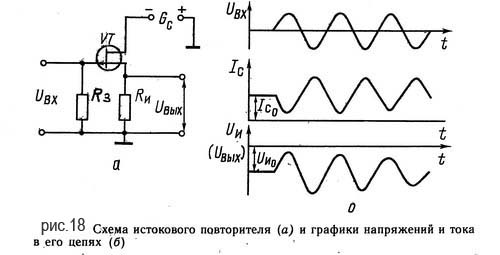
Resistor Rі is connected to the coil, and the stack is directly connected to the negative pole of the life. To that strum drain, which should lie in the input voltage, creating a voltage drop only on the resistor Rі. The work of the cascade is explained by graphs, pointing at Fig. 18, b in the drop-down, if the input voltage is sinusoidal. At the output station, a stream flows through the transistor to the drain I C0, which creates a voltage U І0 (U VIC0) on the resistor Rі. By stretching the positive current of the input voltage, the voltage is reversed between the gate and the coil is increased, so that the stream of the drain and the absolute value of the voltage on the resistor Rі are changed to a change. For a negative voltage period, the input voltage, on the other hand, the voltage of the shutter changes, the flow to the drain and the absolute value of the voltage on the resistor R_ increase. After all output voltage, which is taken from the resistor Rі, then from the cob of the PT (Fig. 18, b), it has the same shape that the input voltage is.
At the connection with cym pіdsilyuvachі іz zagalnoy runoff took away the name of the loop repetitions (the voltage of the coil after the form and the value repeats the input voltage).
High-yield UZCH on field-effect transistors with a turning signal, which compensates.
Today, it is important to cheer up lovers of high-pitched sound creation, or a soldering iron of designers, like they can trim in the hands of power-switched transistors. The majority of such devices, which induce the best light reflections, were inspired by the traditional circuit with a differential input stage and an indifferent additional elements, so as not to take part in the stronger signal, but to ensure the time and temperature stability. It did not change the traditional traditional circuit solutions and zastosuvannya in external cascades of tight complementary transistors with different types of channel conductivity.
As a result of active creative searches and svіdomogo ukilennya in the form of numerical dominating stereotyped scheme solutions, I was able to create my own original prototype of the pilot, which I can minimum quantity electronic components and may vignatkovu stability, superiority and high technical characteristics, building satisfaction to inspire the most famous musical gourmets.
The main parameters of the booster with a voltage support of 8 ohms are shown in the table.
|
Parameter |
Value |
|
|
Coefficient of strength for the pressure |
||
|
Max. |
||
|
Speed of increase in output voltage |
||
|
Frequency range |
20 – 3 0000 |
|
|
Midpoint instability |
||
|
Outside noise voltage |
||
|
Coefficient of non-linear effects |
When rozrobtsі pіdsilyuvacha especially respect was brutally on yakіsnі pokazniki, the maximum KKD and the minimum number of victorious details, which gave the opportunity to suttєvo pіdvishchiti yogo naіynіst that simple repetition. It was also protected by the openness and availability of details at the trading line, which significantly reduced the sociability of the trader.
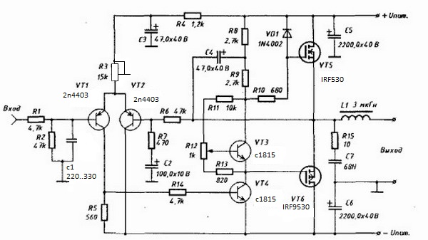
The switch (surprise the circuit) is built from the input stage on low-voltage field-operated transistors different type conductivity VT1 and VT2 are switched on behind the circuit with an overhead turn, and they are driven by resistors R2 and R3. Resistor R1 switches the gates of transistors from the ground and determines the input opir of the power supply, and together with the input capacitor C1 sets the frequency response of the low-frequency region of the sound spectrum. Transistors VT3 and VT4 are connected behind the circuit from the bases; Transistors VT5 and VT6 are connected behind the circuit with a hot collector, their base-emitter transitions are the displacement elements for transistors VT1 and VT2, and change constant voltage on the bases, connected through resistors R7 and R10 with the output of the switch, it compensates for a good sight of the middle point and the growth of the stream is calm. The fall of the constant voltage on the resistors R2 and R3 leads to a strained output transistors VT7 and VT8 by the value of the cob stream drain (quiet stream), which indicates the work of the pilot in class AB.

Scheme pіdsilyuvacha pratsyuє in this way. It is positive that the input signal passes through the capacitor C1 to the gate of the transistor VT1 and causes an increase in the flow of the drain, as a result of which the voltage drop across the resistor R2 increases, which leads to the output of the transistor VT7 and the appearance of a positive signal on the output signal. Through the remote control of the Elementals R7, C2, R8, otko oskuvyluchavach, І EMITINNIY REVIOVAGE ON TRANSISTORI VT5 VT1 Signal Signal, Dіyuchi Yak Negative Swells Zv'. Scho, Scho ComesсуLіsu Luzm Skump middle point. The strengthening of the negative input signal and the stabilization of the parameters is similar to the lower, symmetrical upper half of the circuit. Resistors R4 and R5 together with the input capacities of the transistors VT7 and VT8 make low-frequency filters, which intersect a large amount of bandwidth and achieve self-excitation.
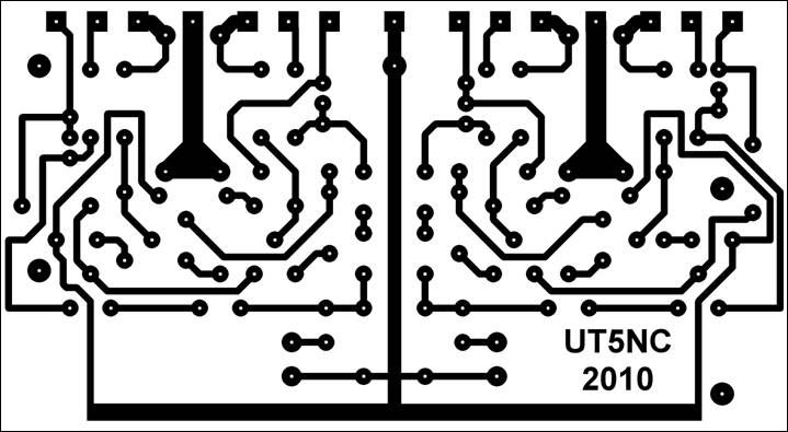
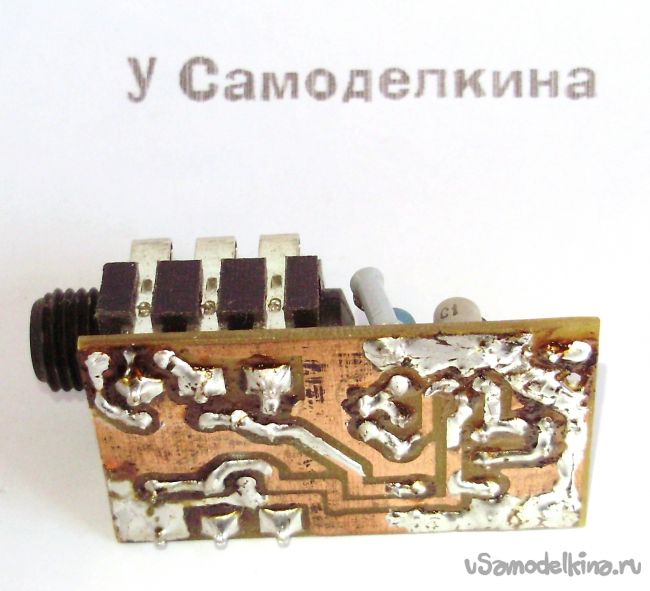
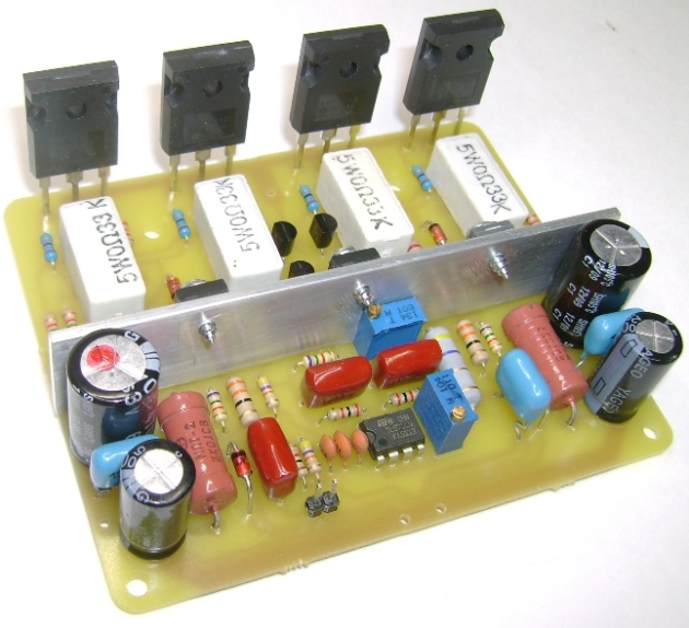
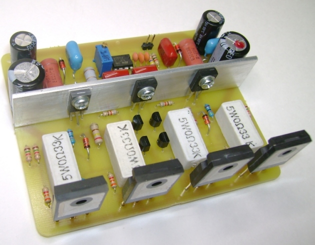
Mounting of the substation is carried out on a different board made of one-sided foil-coated cloth with a size of 115 ´ 63 mm and a thickness of 2 - 3 mm. Below is shown the little ones of the handiwork on the side of the tracks.
The adjustment of the power supply is carried out before the installation of the power supply resistors R2 and R3, calmly through the output transistors, as well as zero voltage at the output of the power supply (middle point). For this, the resistors R2 and R3 are installed at the middle position, the output of the power supply is switched on to a low-voltage lamp of heating with a voltage of 24V and the voltage is supplied. If so, the lamp does not shine, what to say about the correct installation and correct details. Alternately and smoothly wrapping the pressure of substroyuvalni resistors at a higher nominal value, they try to make a struma appear through transistors VT7 and VT8, which is controlled by a digital millivoltmeter for the voltage drop on resistors R11 or R12. The value of the voltage can be in the range of 15 - 20 mV, which indicates a calm struma of 75 - 100 mA. If the middle point at the output of the power supply is shifted at the positive side, then it is installed with a built-in resistor R2, if it is offset at the minus side, then it is installed with a built-in resistor R3. I again control the stream of quiet output transistors and, if necessary, repeat the operation again.
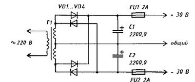
Pidsilyuvach saves its practice when the voltage of life is ±15 to ±30 Volts. It is more necessary to install the live block on a stream of at least 5 Amperes, stabilizer voltage VD 1 and VD 2 on the voltage, which is more than half of the live ones, capacitors C5 and C6 on the air operating voltage, and with a constant robot, the power supply for the maximum output should increase the tension of the resistors R11 and R12 up to 5 watts.
The input transistors VT1 and VT2 are due to the mother equal or close to the cob jet to the IDSS drain. The output transistors VT7 and VT8 must be connected to a close voltage output to the VGS (to) channel, as for this type of transistors it can become 3 to 4 Volts. It is possible to work without intermediary when buying, domiciliating with the seller, and zastosuvav simple self-confident or promiscuous adjuncts. Good types of transistors, shown on the diagram, are paired well, they must be installed on radiators, which can induce exhaustion, through special insulating gaskets. Resistors R2 and R3 are high-turnover precision type SP3-39A, SP5-2 or similar. Electrolytic capacitors C2 and C3 non-polar type, with vicarious impulse block capacitors C5 and C6 should be shunted with non-inductive capacitors with a capacity of 0.1 - 1.0 μF. Resistors R11 and R12 are of the Fuse type, which are shaved when overwhelmed.
One of the main features of the power supply circuit is that the output signal, reinforced by tight transistors, is measured from their drains, which are not electrical electrodes. This made it possible to significantly reduce the specific susceptibility, eliciting an anti-EPC infusion of the sound coil on the output transistors, which means that the signal is heard from both turns or emitters. In this rank, the Danes under the principle of work are equal to the lamp one, but they significantly change it in terms of economy, the width of the smuga of the frequencies, the swidkodity and the supremacy, without seeming to be about the creation of that cost on the components.
An important power of the field transistors are those that, when overheated, the conductivity of their channel changes, the steepness of the characteristics of that stream to the drain decreases, which automatically protects them from thermal breakdown. Another power of field-effect transistors, stagnant at the output stage of the power supply, has a quadratic transient characteristic, as it helps to change the non-linear effects at great equalities of the output pressure. The higher the strum through transistors VT7 and VT8, the greater the coolness of the characteristics and the gain coefficient, and the greater the negative turn signal.
When the power supply is switched on in the measure, until the moment it reaches half the voltage of life on the capacitors C5 and C6, the stabilitrons VD1 and VD2 are closed, and at the same time all the transistors, which are switched on smoothly and simultaneously in both halves of the circuit, are characteristically characteristic. unacceptable bavovna in guchnomovtsі. For reasons of cause, the patient is not afraid of an emergency vimikannya and the inclusion of a voltage of life to wind up for an hour of work on the latest exhaustion.
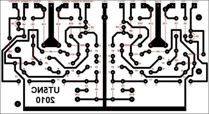
Pіdsilyuvach buv vyprobavânіv robotі z vіznimi dzherel signal, іnіnіh temperatures navkolishny sredovіscha, i vysoka vіdіnіst, vіdmіnі vіhіdnі і dynamic characteristics, і і recommended for repetition by lovers vysokаkіsnoy vysokіsnogo domіno svіdnogo svіzdovіdnja. The block for adjusting the loudness, timbres and balance can be traced to the scheme shown on the site http://cxem.net/sound/tembrs/tembr14.php from the specialized microcircuit TDA1524A. If necessary, before the circuit, you can also add a microphone signal to the signal, which will follow any given circuit. The layout of the details on the plate of the substation is shown below.
The greater the linearity of the power supply and the even greater reduction of the coefficient of non-linear effects is possible by parallel switching on the skin shoulder of two output transistors and the adjustment (to the nominal value) of one of the resistors R 8 or R 9 in the lance zvorotny zv'azku. To remove the transitional capacitor C 1, the circuit can be converted to a tight linear substation of a constant jet for automation systems, telemechanics and control.
Yurko Strelkov-Serga
PO Box 5000 Vinnitsa-18
[email protected]
Technical characteristics
Maximum root-mean-square tension:
at RH = 4 Ohm, W 60
at RH = 8 Ohm, W 32
Working frequency range. Hz 15...100 000
Coefficient of non-linear actions:
at f = 1 kHz, Рvih = 60 W, RH = 4 Ohm, % 0.15
at f = 1 kHz, Рvih = 32 W, RH = 8 Ohm, % 0.08
Gain coefficient, dB 25...40
Input impedance, room 47
Nalashtuvannya
It’s small, but it’s difficult for an experimentalist to achieve good results when prompted to follow the scheme. Head problems, such as the following transfer - tse incorrect installation of elements and the failure of MOS transistors when they are incorrectly driven or when the circuit is damaged. As a curiosity for the experimenter, the offensive rewriting of control rechecks for the sake of faults is suggested:
1. Under the hour of folding the other one, pay the order to install the passive elements and switch over to the correct polarity of the electrical capacitors. Let's install transistors VT1...VT4. І, nareshti, install MOS transistors, uniquely statically charged, flickering one hour to the ground and soldering iron. Check the selected fee for the correctness of the installed elements. For whom it will be koristuvatisya roztashuvannyam elements, we will show in fig. 2 Reverse the drukovani pay for the daytime, solder the tracks and, like the stench, remove them. Reverse the rations visually and electrically for the help of a multimeter and rework, as it is necessary.
2. Now the voltage supply can be applied to the substation and it is set to the stream of the calm output stage (50 ... 100 mA). The R12 potentiometer will be set to the minimum for the minimum stream of calm (up to the counter arrow on the topology of the board, Fig. 2). the positive life switch turns on the ammeter with a boundary of 1 A. The wrapper of the resistor R12 motor reaches the ammeter reading of 50 ... 100 mA. The installation of a struma can be calm but vikonan without a connection to the venture. However, as a naive dynamic of inclusions in the circuit, it is guilty of thefts by the defender in the form of fast strum. When the stream is installed calmly, the value of the external voltage used may be less than 100 mV.
Zayvі or bezpalnі change the struma of calm when adjusting R12 indicates faulty generation in the circuit or incorrectly zadnannya elements. Follow the recommendations described earlier (after switching on the resistors to the lantern of the gate, minimizing the duration of the conductors, earthing). In addition, the decoupling capacitors are installed in direct proximity to the outgoing cascade, which is the grounding point of the voltage. To get rid of overheating tight transistors regulation of the struma can be easily adjusted when installed on thermally driven MOS transistors.
3. Once the ammeter is installed, the ammeter can be removed
from the lance of positive life, and at the entrance, you can buti
a working signal has been given. The value of the input signal for derivation of the total nominal tension can be as follows:
UBX = 150 mV (RH = 4 ohms, Ki = 100);
UBX = 160 mV (RH = 8 ohms, Ki = 100);
UBX = 770 mV (RH = 4 ohms, Ki = 20);
UBX = 800 mV (RH = 8 ohms, Ki = 20).
"Pіdіzannya" at the peaks of the output signal during operation with nominal intensity indicates the filthy stabilization of the voltage of life and can be corrected by a decrease in the amplitude of the input signal and a change in the nominal characteristics of the power supply.
The amplitude-frequency characteristic of the substation can be overridden in the frequency range of 15 Hz ... 100 kHz for an additional set for sound testing or a generator and an oscilloscope. The emergence of the output signal at high frequencies indicates the reactive nature of the input and for the restoration of the signal form, the value of the inductance of the output inductor L1 is needed. The amplitude-frequency characteristic at high frequencies can be controlled by an additional compensation capacitor connected in parallel with R6. The low-frequency part of the amplitude-frequency characteristic is corrected by the elements R7, C2.
4. The presence of the background (buzz) is more relevant to the scheme
when installing over a high building. Pointing at the entrance to the high
the impedance minimizes the screened
cable grounded at the signal socket. Low-frequency pulsations of life, which are consumed from life at the input cascade
podsilyuvacha, can be used by the capacitor SZ. Dodatkovo
attenuation of the background is caused by a differential cascade
on transistors VT1, VT2 pіdsilyuvacha. However, as the background is the voltage of life, it is possible to choose the value of SZ, R5 to suppress the amplitude of the pulsations.
5. At the time of the output of the fret of the transistors of the output cascade through short hum at the beginning, or through high-frequency generation, it is necessary to replace the MOS transistor, with which it is small, so that other elements come out of the fret. When installing the scheme of new appliances, the procedure for adjusting the fault is repeated.
Scheme of the living block
The best constructions of "Radioamator" Issue 2
Scheme pіdsilyuvacha іz zminami:

This attachment allows you to connect a dynamic microphone, an electric device and other devices to a signal with a high output support to the computer's sound card. Attachment is not to introduce frequency effects in the audio frequency range, as well as the effects associated with the non-linearity of the subsilience adjustment, the shards are prompted for the repetition scheme.
In other words, if you want a little bit of turbulence and the quality of the sound that is being recorded, you have a bad sound card and an expensive microphone, then all the attachments are those that you need.
Trohi about the scheme. The attachment is starting to work, as a monojack is inserted into rose J1, or, as scientifically, a plug with a diameter of 6.35 mm (1/4 inch). When this happens, through the jack, the minus contact of the battery switches to minus life and starts the robot. Also, the other contact of this plug, the input signal is sent to the resistor R1, which ensures a high input support. Capacitor C2 to carry out frequency adjustment, forming frequencies higher than the audio range. Resistors R2-R4 provide the necessary voltage at the gate of the field-effect transistor.

This design has a polov transistor KP303 with index E. With a different transistor with a lower index, it is possible to change the rating of resistors R3 and R4. Resistor R5 є navantazhennyam pіdsiluvalnogo cascade, z new sound signal znіmaєєtsya capacitor C5 through the resistor R7 is fed to the input of the sound card of the computer.
Diode VD1 in the circuit wins the function of protection against a fool in the form of a reversed polarity reversal, shards design features rose batteries "Krona" do not include such capability. The diode is more likely to zastosuvat germanium, the shards of the drop in voltage on the new one will be smaller. But it’s not critical, it can be replaced by a low-voltage silicon diode, for example, KD521, KD522, 1N4148, etc.
Attachments are selected on a plate from a single-ball foil textolite with a size of 47x26mm. Tracing the payment in the Dip Trace program will be hovered lower. Ale, you can get by and pay without making a payment, and pick up everything on a universal mounting plate (the price is the same as with a couple of darlings) of the same size.
![]()
The body will be built from a single-ball textolite for a complete screening of the substation.
Expand the yoga details as follows:
- side walls 60x50 mm - 2 pieces
- front wall 50x30 mm - 1 piece
- Back wall 46x30 mm - 1 piece. Size 46 mm is not critical, it can be varied from 50 mm to 35 mm. Keep everything in order, as you would like to install a battery of life.
- lower and intermediate walls 55x30 mm
The walls of the body are soldered together with solder. Foil on all walls can be folded into the middle of the body. Try not to overheat the textolite, the shards of the foil can be easily broken.
All the walls are soldered to each other in front of us, the rear crimson. Then drilled open for a rose jack with a diameter of 10 mm, an opening for live wires, here 3 mm at a diameter and also at the back wall for a screened door with a minijack.
Also, at the place of fastening of the back wall, a bracket is soldered to the tow honey dart, into the yak, insert the bottom of the back wall.
If necessary, you will need to glue roses for Kronya. Before the speech, you can take it from the crown, which you have already practiced, as I will work and work. To be glued with pink hot-melt adhesive to the back side of the front wall. It is important that you can get out of contacts without touching the foil to the case.
Dekіlka words about pardons for installation:
In order to improve the readability of the circuits, we consider the voltage intensities with two pairs of terminal field-effect transistors and a voltage of ±45 V.
As a first pardon, we will try to "solder" the stabilitrons VD1 and VD2 with the wrong polarity (correct inclusion is shown in small 11). The map is awake to look at the little one 12.
Figure 11 The pinout of the BZX84C15 stabilitrons (the same pinout on the diodes).
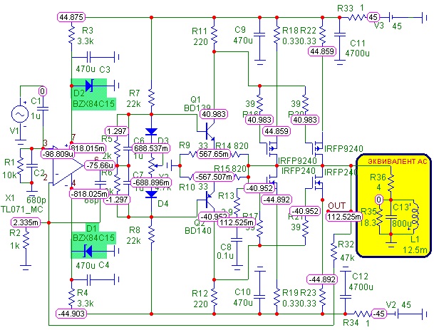
Figure 12 The map of the tension of the tension suppressor in case of improper installation of the stabilitrons VD1 and VD2.
These stabilizers are needed for forming the voltage of the life of the operational pilot and are selected by 15 exclusively through those that the voltage is optimal for this operational pilot. Pratsezdatnіst without wasting power pіdsilyuvach zberіgaє і in case of vikoristannі order nominalіv, scho to stand on the line - at 12 V, at 13 V, at 18 V (but not more than 18 V). In case of improper installation, the replacement of the voltage of the life, the operating pressure switch, will take away only the voltage of the drop on n-p transitions stablіtronіv. The strum is still regulated normally, at the output of the substation there is a small constant voltage, the output signal is external.
It is also possible to incorrectly install diodes VD3 and VD4. In this case, the strum is calmly separated by less than the ratings of resistors R5, R6 and can reach a critical value. The signal at the output of the power supply will be, but to finish the heating of the terminal transistors, it will unequivocally cause their overheating and the output of the power supply will be out of whack. The map of voltages and streams for the purpose of pardon is shown in Figure 13 and 14.

Figure 13 Map of the voltage of the booster in case of improper installation of thermal stabilization diodes.
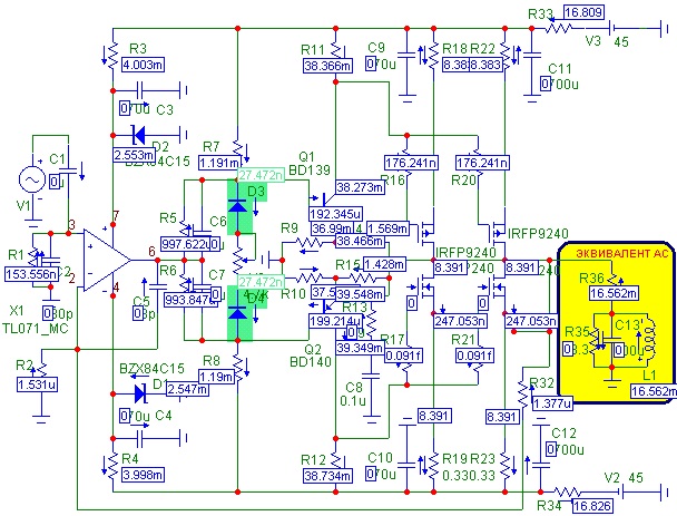
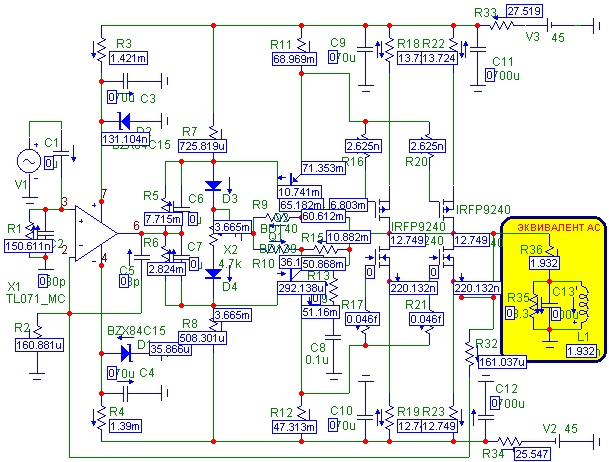
Malyunok 14 Mapa strum_v p_dsilyuvacha in case of improper installation of diodes of thermostabilization.
An offensive popular pardon for installation is the incorrect installation of transistors in the front cascade (drivers). The map of the voltage of the power supply in this direction is growing at a glance, shown in the figure 15. In this direction, the transistors of the terminal cascade are completely closed and at the output of the power supply it is possible to see if there is a sign of sound, and the level of the constant voltage is maximally close to zero.
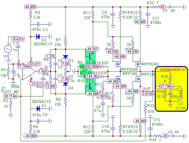
Figure 15 Voltage map with incorrect mounting of transistors in the driver stage.
They gave the most safe pardon - the transistors of the driver cascade were confused by the mists, and the pinout was also confused after what is added to the transistors VT1 and VT2 - we believe and the stench works in the mode of the mother repeater. At this point, the strum through the terminal cascade should lie in the position of the motor of the substring resistor and it may be up to 10 to 15 A, so in any case, the changeover of the block of life and the switching of terminal transistors. On the little 16 shows the jet at the middle position of the substring resistor.
Malyunok 16 Strum card with improper installation of transistors in the driver cascade, the pinout is tangled.
It is unlikely that you can solder the ends of the field-operated transistors IRFP240 - IRFP9240, and remember the axis often. In this way, diodes are installed in the transistors in a difficult situation - the voltage that is given to them, the polarity can be given to their minimum support, which means the maximum slowdown in the block of living and how fast the stench will win more luck in the future
Fireworks on the board can also be due to one reason - for sale, flashing 1.3 W stabilitrons in the case is the same as in 1N4007 diodes, so before installing the stabilitrons on the board, as the stench in the black case, it is more important to familiarize yourself with the inscriptions on the case. During installation, the replacement of stabilizer diodes of diodes, the voltage of the operating power supply is surrounded by only the ratings of the resistors R3 and R4, and by the strum of the operating power supply itself. In any case, the magnitude of the voltage, which was, is significantly greater than the maximum voltage of the life for this OS, but the thrust of this winding is in harmony with the part of the body of the OS itself, well, far away, it is possible to have a constant voltage on the output, close to the life pressure pіdsilyuvacha, scho to cause the appearance of a constant strain on the exit of the most pіdsilyuvacha of tension.
Well, and finally, a few words about the ratings of resistors R3 and R4, which should lie in the voltage of the life of the power supply. 2.7 kOhm is the most versatile, however, when powered by a voltage of ± 80 V (only for 8 Ohm voltage), these resistors will be close to 1.5 W, so you need to replace it with a resistor of 5.6 kOhm or 6.2 kOhm, so reduce the vision thermal exhaustion up to 0.7 W.


Starry look modifications of induction tension induction in the photographs below:

Lost in a barrel of honey squish a spoonful of dogtu.
On the right, in the fact that the polytransistors IRFP240 and IRFP9240, which are used in the power supply, the International Rectifier (IR) retailer pinned the release, as it gave more respect to the quality of the products that were released. The main problem of these transistors is that the stench was broken up for victorious use in the living quarters, but it turned out to be a whole accessory for sound subsonic equipment. Promoted respect to the density of the components, which are released from the side of the International Rectifier, it allowed, without vibrating the transistors, to turn on the transistors in parallel, without worrying about the power characteristics of the transistors - the switch without exceeding 2%, which is generally acceptable.
Today, the IRFP240 and IRFP9240 transistors are manufactured by Vishay Siliconix, as it is not so reverently placed on products, which are allowed and the parameters of the transistors have become more adjunct to life - the rise of "coffee power" transistors in one batch exceeds 1%. This does not include parallel connection without a front selection, and the number of overturned transistors for the selection of 4 however, exceeds a dozen copies.
At zv'yazku z tsim before folding this pіdsilyuvacha nasampered z'yasuvati, which firms of transistors you can get. If your stores have Vishay Siliconix for sale, it is recommended that you take a look at this pressure drop - you risk to take it seriously and do not reach anything.
However, the work of the "VERSІЇ 2" expansion of the low intensity and the presence of decent and not expensive field-operated transistors for the output cascade made the trochs fade over the possible circuitry. As a result, "VERSION 3" was modeled, which replaced the field-effect transistors IRFP240 - IRFP9240 by Vishay Siliconix with a bipolar pair like TOSHIBA - 2SA1943 - 2SC5200, which is still quite decent quality.
Schematic diagram a new version of the pilot removed the additional "VERSІІЇ 2" and recognized the change in the output cascade, allowing the modification of the field transistors. The principle diagram is shown below:
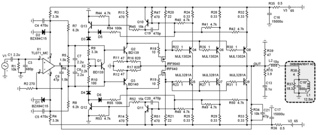
Principal diagram for the selection of field-operated transistors as repeaters ZBILSHIT
In this way, the polovі transistors were saved, but the stench zastosovuetsya like repeating the voltage, which means the driver cascade is reversed. A small positive link has been introduced into the system of zakhistu, which allows the awakening of pidsiluvach tension between spratsovuvannya zakhistu to disappear.
There is a fee in the process of distribution, based on the results of real experiments, and a practical fee is charged for appearing at the end of the leaf fall, but for the time being, you can request a schedule for the elimination of THD, the elimination of MICROCAP. You can read a report about this program.


