Electronic impulse drive based on TL494. Management of power transistors with a microcircuit tl494
All electronics engineers who are engaged in the construction of electrical installations, sooner or later face the problem of the presence of the equivalent of the charge, or the functional exchange of the charge, and the very dimensions. Fortunately, the appearance on the Russian market of cheap and hard-wired field-operated transistors managed to correct the situation.
Steel z'yavlyatisya amatorskі konstruktsії Electron navantazhen on bazі polovih tranzistorіv, bіlsh pridatnih to vikoristannya yak Electron opіr, nіzh їh twin bіpolyarnі: Temperature maintained upstream stabіlnіst, practical nulovy opіr channel at vіdkritomu stanі, malі Stroomi upravlіnnya - osnovnі perevagi scho viznachayut perevagu component regulyuyuchogo at tight outbuildings. Moreover, the most intriguing propositions have appeared in the field of fixtures, the prices of which explain the most intriguing models of electronic inventions. Ale, shards of pickers orient their foldable and richly functional products under the name "electronic vanity" mainly on the versatility, price on the price of flooring high flooring, so you can afford to buy it as much as possible. It's true, I don't understand, - there is a lot of people who are electronically motivated.
The EN of industrial production, oriented to the amateur engineering sector, was not marked by me. So, I’m going to do all the work myself again. E-ex ... Well, it's okay.
Advantages of the electronic equivalent of the advantage
Why, in principle, electronic navantage equivalents are better than traditional devices (strength resistors, heating lamps, thermal heating and other attachments), which are most often chosen by designers when various power devices are loaded?
Crowds of the portal, yakі ossuyuyutsya konstruyuvannya that repair blockіv zhivlennya, bezsmnіvnіvnіvіvnіvnіvі know vіdpovіd tse pitannya. I especially want two factors that are enough for my mother to have electronic interference in her "laboratory": small dimensions, the ability to control the intensity of interference at great boundaries in simple terms(so, as we regulate the volume of the sound, or output voltage to the block of life - with a sizable replacement resistor, and not with the hard contacts of the knife switch, the dvigun of the rheostat, etc.).
In addition, the "dії" of electronic navantage can be easily automated by making it easier in such a rank and by making thinner tests of the power unit for the help of electronic navantage. At the same time, zrozumіlo, the eyes of the engineer's hands are fluttering, the robot becomes productive. Ale about adding all the possible twists and turns - not in this article, and, perhaps, according to another author. In the meantime, - there is only one different type of electronic drive - impulse.
Features of the pulsed version of EN
Analogue electronic input is insanely good and richly quiet, who, having won the EH when power devices were adjusted, appreciated these advantages. Impulse EH may have its own peculiarity, giving the possibility of evaluating the work of the life unit with the impulsive nature of the impulse such as, for example, a robot of digital attachments. The pushing of the sound frequencies booster so itself gives a characteristic surge to the extension, and that, it would not be bad to know, how the block of living, refinancing and preparations for a specific booster, with a predetermined nature of the pressure, will behave.
When diagnosing blocks of life that are being repaired, the effect of stopping the pulsed EH is so memorable. So, for example, for the help of a pulsed EH, an incompatibility of the current computer PSU was revealed. The inadequacy of this 850-watt power supply unit was declared to be offensive: the computer with a robotic s cim BP was mimicking quite a bit at any hour with a robot, be it an addendum, independently in the presence of a tightness, at the time of withdrawal. In case of a change in voltage (a bunch of tension resistors + 3V, + 5V and halogen bulbs of + 12V each), the power supply unit turned out to be "cheers" for a short period of time, despite the fact that tension tension folded 2/3 of the declared tension. The fault appeared when the pulsed EH was connected to the +3V channel and the power supply started to turn on, the ammeter needle reached the 1A socket. With this stream, the tension of the skin from the other channels of the positive voltage did not exceed 3A. The supervisor's board turned out to be faulty and was replaced with a similar one (fortunately, it was the same power supply unit with a power part that it failed), after which the power supply unit earned normally at the maximum stream allowed for a vicarious copy of the pulse EN (10A), which is the subject of description in the data stat.
Idea
_Deya Watery Impulse Navaltezhennaya ZAAVYAYA DISABLE WITHOUT HOW BULA ROALIZED IN 2002 ROTSI, ALLE NOT IN THE MODIOCHNY ї ї і і і і іншій і ї і і і і інель и і і not bully for that hour . Narazі zіrka to stand іnakshe і schos zіyshlos for chergovy vіlennya tsgogo pristroy. On the other side, little more than a little more recognized - rechecking the parameters of pulse transformers and throttles. But you don’t care about one alone. Before we speak, if you want to work on the relevant inductive components for additional or similar equipment, be kind: below for the archives of articles of masters (in the gallery of power electronics) engineers related to these topics.
Otzhe, why is it "classical" (analogue) EN in principle. Strumovy stabilizer, which works in the mode of short hum. I nothing more. I will be right of the one who, in a fight, be-like addiction, close the weekends charger outbuilding abo zvaryuvalnogo device and say: tse - electronic navantazhennya! It’s not a fact, obviously, that it’s similar to the mite of harmful consequences, like for attachments, and for the operator himself, but also that and other attachments effectively and as a whole could claim the role of electronic immersion, just like The other skilki was always primitive and drank the strum. Strum analog EH stale in the output voltage is changed by the PSU, ohmic support to the field-effect transistor channel, which is set by the value of the voltage on the gate.
Strum in the pulse EH is dependent on the sum of the parameters up to which will include the width of the pulse, the minimum support for the critical channel of the output key and the power of the tested PSU (capacitor capacity, PSU inductance, voltage output).
When the key is opened, the EN is approved for a short time short chirp, When the capacitors of the tested PSU are discharged, and the throttles (as the stench is in the design of the PSU) are energized. Classic short circuit, prote, no, because the width of the pulse is surrounded by microsecond values, which determine the value of the discharge jet of the capacitors of the power supply.
At that very hour, the re-verification of the pulse EN is extreme for the tested PSU. Then, and "water stones" with such a reversal, they appear more, right up to the viability of the conductors, to revive, to bring to the life-giving extension. So, with a pulsed EH connected to a 12-volt PSU, we can middle wires lived with a diameter of 0.8 mm and a stream of tension 5A, an oscillogram on the EH showed pulsations, which are a sequence of rectilinear impulses with a range of up to 2B and gostrokintsevic waves with an amplitude that is healthy for the tension of life. On the terminals of the BP itself, pulsations in the EN were daily. On samіy EN pulsatsії boule zvedenі to mіnіmumu (less then 50mV) for Relief zbіlshennya kіlkostі I lived skin zhivlyachih EN provіdnikіv - up to 6. "dvozhilnomu" varіantі mіnіmumu pulsatsіy, porіvnyannogo of "Six-conductor", its orientation away dosyagti dodatkovogo elektrolіtichnogo capacitor єmnіstyu 4700m zhivlyachih provodіv іz vanity. Also, if you have a BP, the EH impulse may be needed.
Scheme
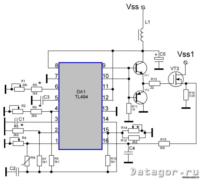
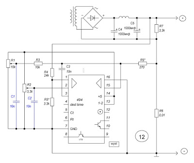
EN is based on popular (there is a large number of recyclable computer PSUs) components. Scheme EH to replace the generator with a regulated frequency and pulse width, thermal shock. Wickon generator on PWM TL494.
Frequency regulation is controlled by a changeable resistor R1; sparing - R2; thermosensitivity - R4; frothing of the struma - R14.
The output of the generator is forced by a semi-terminal repeater (VT1, VT2) for operation on the gate capacity of field-effect transistors in the number of 4 or more.
Generator circuit and buffer stage on transistors VT1, VT2 can be powered by okremy dzherel living with a voltage of +12...15V and a strum up to 2A, or the power supply is changed to the +12V channel.
Exit EH (field-effect transistor stik) and connect with "+" the PSU is checked, the EH wire is connected to the PSU wire. The skin of the gates of the field transistors (at the same time as the group switch) is responsible for the connection with the output of the buffer stage by a wet resistor, which reduces the difference in the parameters of the gates (sustainability, limiting voltage) and ensures safe synchronous operation of the keys.
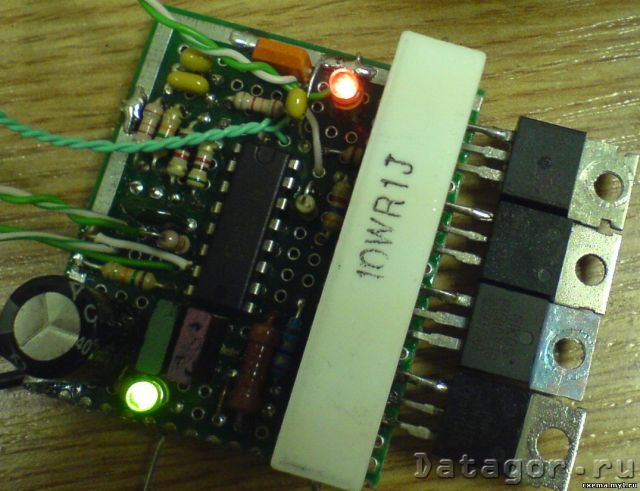
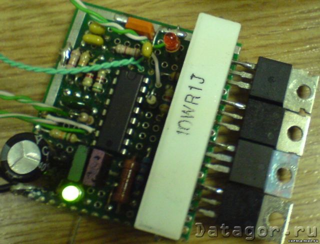
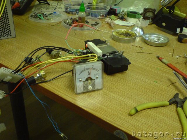
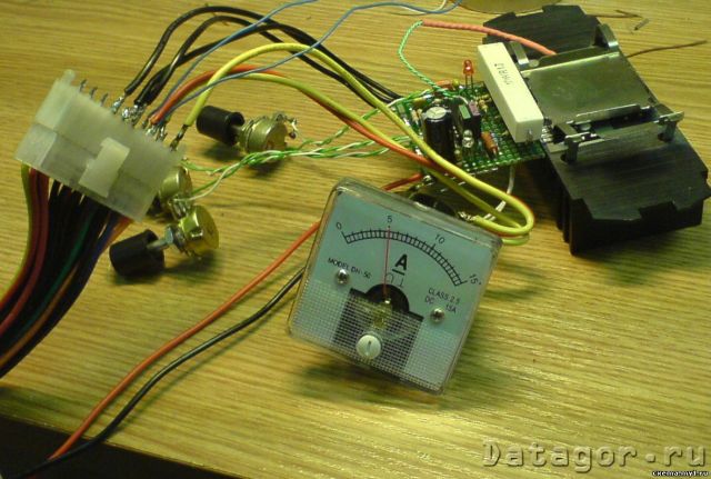
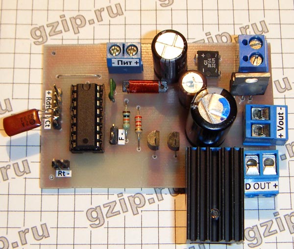
The photographs show that on the EH board there is a pair of light diodes: green - an indicator of liveliness of heat, red - indicates the protection of the microcircuit at a critical temperature (constant light) or an exchange of struma (ice remember the measure). The operation of the red light diode is controlled by a key on transistors KT315, the emitter of any kind of connection from a glowing drotom; base (through a 5-15kΩ resistor) with 3 microcircuits; the collector - (through a 1.1 kΩ resistor) with the cathode of the light diode, the anode of some kind of connection with 8, 11, 12 DA1 microcircuits. On the scheme, there are indications, because not obov'yazykovym.
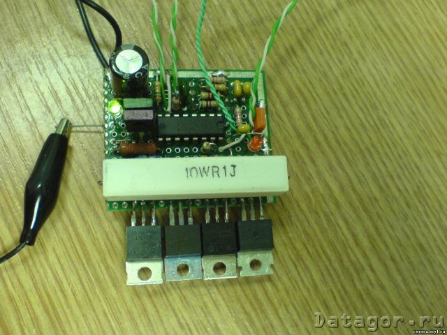
shodo resistor R16. When passing through a new struma 10A, it is rozsіyuєtsya on the resistor attenuation stock 5W (when indicated on the support diagram). In a real design, a resistor with a support of 0.1 Ohm is used (there was no required nominal value) and the intensity, which is rozsіyuєtsya on the first case, with that stream, a warehouse of 10W. The temperature of the resistor at the same time is rich for the temperature of the keys EN, yak (with a different radiator, shown in the photo) does not heat up much. Therefore, it is better to install the temperature sensor on resistors R16 (otherwise in a non-intermediate proximity), and not on a radiator with EH keys.
ARCHIVE:
Zagalny description of the victoria
TL 494 that її coming version - most often zastosovuvana microcircuit to encourage two such transformations of life.
- TL494 (original Texas Instruments) - ІС ШІМ voltage changer with single-cycle outputs (TL 494 IN - DIP16 case, -25..85С, TL 494 CN - DIP16, 0..70C).
- K1006EU4 - analogue of TL494
- TL594 - analogue of TL494 with improved accuracy of pardons and comparators
- TL598 - analogue of TL594 with two-stroke (pnp-npn) repeater at the output
Reference material - information on the topic of the original technical document Texas Instruments, publication of International Rectifier ("Power supply devices of International Rectifier", Voronezh, 1999) and Motorola.
Advantages and shortcomings of this microcircuit:
- Plus: Separate lances of control, two differential inputs (they can also override logical functions)
- Minus: Single-phase outputs require additional watering (paired with UC3825)
- Minus: Inaccessible to the strum, keruvannya, a visible loop zvorotny zv'azku(non-critical in car PN)
- Minus: Synchronous inclusion of two and more ІС is not so convenient, like that of UC3825
1. Features of microcircuits TL494
Lanzyugi ІONu ta zakhistu vіd nedoprugi zhivlennya. The circuit turns on when the threshold 5.5..7.0 is reached (typically 6.4V). Until this moment, the internal control bus is blocked by the generator robot and the logical part of the circuit. Idling jet at +15V voltage (turned on transistors) not more than 10 mA. ІОН +5V (+4.75..+5.25 V, output stabilization not higher than +/- 25mV) secures strum up to 10 mA. It is possible to use ION only with a vicorous npn-emitting repeater (div. TI st. 19-20), but at the output of such a "stabilizer" the voltage is strongly stale in the stream of stress.
Generator vibrating on the clock-setting capacitor Ct (visnovok 5) saw-tooth voltage 0..+3.0V (amplitude set by ІON) for TL494 Texas Instruments and 0...+2.8V for TL494 Motorola (why checks for others?), suitable for TI F =1.0/(RtCt), for Motorola F=1.1/(RtCt).
Permissible operating frequencies from 1 to 300 kHz, with the recommended range of Rt = 1...500kΩ, Ct=470pF...10mkF. With this, the typical temperature drift of the frequency becomes (naturally, without adjusting the drift of the overhead components) +/-3%, and the frequency in the fallow period due to the voltage of life is within 0.1% of the entire allowable range.
For remote switch-off of the generator, it is possible to close the input Rt (6) to the output of ІON by the external key, or close Ct to the ground. Obviously, the opir coil of the open key can be protected for the choice of Rt, Ct.
Entrance to the control of the resting phase (springiness) through the phase comparator, I set the necessary minimum pause between pulses at the shoulders of the circuit. It is necessary to prevent a scratchy strum in the power cascades of the ІС position, so the stable operation of the trigger - the hour of the TL494 digital part switching becomes 200 ns. The exit signal of permissions is the same, if the saw on Ct shifts the voltage at the input of the power 4 (DT). At clock frequencies up to 150 kHz at zero electrical voltage, the rest phase = 3% of the period (equivalent to a shift in the electric signal of 100 ... 120 mV), at high frequencies, a correction was made to expand the rest phase to 200 ... 300 ns.
You can turn on the DT input, you can install a fixed quiet phase (R-R timer), soft start mode (R-C), remote muting (key), and also turn DT as a linear key input. The input lance is selected on pnp-transistors, so the input stream (up to 1.0 μA) winds from the IC, and does not plug into the new one. Strum dosit great, to that the uniqueness of high-ohm resistors (no more than 100 kOhm). At TI, side. 23, the butt of the defense against the overvoltage was pointed to the vikoristannyam of the 3-wire zener diode TL430 (431).
Pіdsilyuvachi pardons- Vlasne, operational substation with Ku = 70 ... 95dB on constant pressure (60 dB for early series), Ku = 1 at 350 kHz. The input lances are selected on pnp-transistors, so the input stream (up to 1.0 μA) flows from the IC, and does not stick into it. The strum is great for an op-amp, the voltage used is tezh (up to 10mV), so there are unique high-resistance resistors in keruyuchy lances (three more than 100 kOhm). Then, the zavdyaki vykoristannyu pnp-inputs range of input voltage - vіd -0.3V to Vzhivlennya-2V.
Come out two pidsilyuvachiv to eat one of the ABO. That pidsiluvach, on the way out more voltage, overriding the control logic In this case, the output signal is not available, but only from the output of the diode ABO (in the same input of the pardon comparator). In this way, only one switch can be closed by the OS loop in the linear mode. Tsey pіdsilyuvach i zamikaє golovna, liniynu OS s vyhіdnoї naprugi. Another pіdsilyuvach with tsomu can vikoristovuvatisya like a comparator - for example, relocating a vented stream, or as a key to a logical alarm signal (overheating, short circuit toshcho), remote viknennya that іn. One of the inputs of the comparator is connected to ІON, on the other, a logical ABO of emergency signals is organized (more briefly - logical and signals of normal states).
For example, the RC frequency-dependent OS has a trace of memory, which the output of the power supply is actually single-cycle (last diode!) The voltage at this output is in the range of 0..+3.5V (three times larger than the range of the generator), then the voltage coefficient drops sharply and at about 4.5V, the voltage drops at the output. Similarly, the next uniqueness of low-resistance resistors in the lances is the output of the subsiluvacs (OS loops).
Subsidiaries are not approved for operation within one cycle of the operating frequency. When the signal width is jammed in the middle of the pulse waveform in 400 ns, the stink for the second one is more correct, that trigger control logic does not allow (there would be side pulses on the output). In real PN circuits, the frequency of the lancet OS vibraetsya close to 200-10000 Hz.
Trigger and output control logic- If the voltage is not less than 7V, then the voltage was drunk on the generator more low at the input of DT, which is controlled, and the voltage was drunk more low to be sure of the pidsiluvachіv pardon (with the improvement of the vbudovannyh thresholds and zsuvіv) - the scheme is allowed. When the generator drops to the maximum zero - outputs turn on. Trigger with paraphase output doubles the frequency. With a logical 0 at input 13 (output mode), the phases of the trigger are combined with ABO and are applied one hour to the exit, with a logical 1 - they are applied paraphase to the skin exit okremo.
Exterior transistors- npn Darlingtoni with a warm zakhist (ale without a zakhist strum). In this way, the minimum voltage drop between the collector (usually closed to the positive bus) and the emitter (on the input) is 1.5V (typically at 200 mA), and for the circuit with a glowing emitter, it is three times shorter, 1.1 V typical. The boundary output stream (with one open-circuit transistor) is 500 mA, the boundary pressure of the entire crystal is 1W.
2. Features of stosuvannya
Robot on the gate of the MIS transistor. Weekend repeaters
When working on the єmnіsne navantage, as if mentally є the gate of the MIS transistor, the output transistors TL494 are switched on by the omіternim repeater. When the average stream is exchanged at 200 mA, the circuit is designed to charge the gate quickly, but it is impossible to discharge it with a switched-off transistor. Discharging the gate behind the help of a grounded resistor is also not enough. And then the voltage at the gate capacitance drops exponentially, and the transistor shutting down the gate needs to be discharged at 10V three times more than 3V. Strum discharge through the resistor, so there will be less charge through the transistor (the resistor will not be weakly heated, and steal the key strum when going uphill).
Option A. Lanciug in a row through the old pnp transistor(Positioned on Shikhman's website - div. "Block of life for the life of Jensen"). When the gate is charging, the strum that flows through the diode closes the active pnp transistor, when the IC output is turned off, the diode closes, the transistor turns on and discharges the gate to the ground. The minus is that it works only on small capacities of vanishing (surrounded by a streaming reserve of the output transistor IC).
With vikoristanny TL598 (with two-stroke output), the function of the lower discharge arm is already sewn on the crystal. Option A is in some way not correct.
Option B. Independent complementary repeater. Oskilki main strumovo vanity with the help of an external transistor, the capacity (strum charge) of the charge is practically not limited. Transistors and diodes - be it HF with a small amount of pressure and Ck, and a sufficient supply of struma (1A in pulse and more). For example, KT644+646, KT972+973. "Earth" repeating is guilty of being soldered without intermediary instructions from a coil of a power key. Collectors of transistors are repeating, shunting the ceramic capacitor (not shown in the diagram).
How to choose a scheme - to lay it in front of the nature of the bias (shutter release or charge switching), the operating frequency, the timing could be up to the front of the impulse. And the stench (front) is guilty of buti yaknaishvidshe, even at the transitional processes on the MDP keys, a greater part of the heat inputs is displaced. I recommend that you turn to the International Rectifier collection before publication for a complete analysis of the task, and I will cut myself off with a butt.
The exhaust transistor - IRFI1010N - may have a second pre-charge charge on the gate Qg=130nC. Tse chimalo, even the transistor may be vinyatkovo great square channel to ensure an extremely low support for the channel (12 mΩ). The very same keys and needs in 12V turnarounds, de leather a million on a rahunka. To ensure that the channel is open, the gate requires Vg = + 6V to earth, moreover, the total gate charge is Qg (Vg) = 60 nC. Shchob is guaranteed to discharge the shutter, charging up to 10V, the need for recharging Qg (Vg) \u003d 90 nC.
2. Implementation of the strum, soft start, fencing
As a rule, for the role of the strum sensor, it is also necessary to ask for the last resistor from the lance navantage. Ale wines are more expensive volts and cotton wool at the exit of the reworking, that and control is less than lances of interest, and it is not possible to detect short circuits in the first lances. Solution - inductive sensor for the struma of the primary lancet.
Vlasne sensor (strumu transformer) - a miniature toroidal coil (internal diameter is to blame, sensor winding cream, you can skip the wire of the primary winding of the main power transformer). Crisis tore is passed through the primary winding of the transformer (but not "earthing" through the coil!). The constant rise time of the detector is set on the order of 3-10 periods of the clock frequency, the fall - 10 times more, depending on the stream of the optocoupler (about 2-10 mA with a voltage drop of 1.2-1.6V).

The right side of the circuit has two typical solutions for TL494. Dilnik Rdt1-Rdt2 sets the maximum sparing (minimum calm phase). For example, at Rdt1=4.7kΩ, Rdt2=47kΩ at output 4 constant voltage Udt=450mV, which is in quiet phase 18..22% (deposit in series IV and operating frequency).
When live Css discharges are on and the potential at the input DT is higher than Vref (+5V). Css is charged through Rss (out there Rdt2), smoothly lowering the potential DT to the lower boundary, surrounded by a dilnik. Tse "soft start". At Css=47uF and the assigned resistors, the circuits turn off after 0.1 s after being turned on, and enter the working spool with a stretch of 0.3-0.5 s.
The circuit, crim Rdt1, Rdt2, Css has two turns - a stream of an optocoupler (no more than 10 μA at high temperatures, about 0.1-1 μA at room temperature) and a stream to the input DT of the base of the input transistor IC. So that these streams did not exactly add to the accuracy of the dilnik, Rdt2 = Rss is chosen no more than 5 kOhm, Rdt1 - no more than 100 kOhm.
Zrozumilo, choose the same optocoupler and lance DT for managing inconsistencies. It is possible to switch off the pardon in the comparator mode, and blocking the capacitance or the generator resistor (for example, by the optocoupler itself) - but also turning it off, and not smoother exchange.
Tіlki nagolovnishe.
Life voltage 8-35V
Ability to work in single-cycle and two-cycle modes.
For a single-cycle mode, the maximum momentum valority is 96% (less than 4% dead hour).
For the two-stroke option, the dead time cannot be less than 4%.
By supplying whiskers 4 voltage 0 ... 3.3 V, you can regulate the dead hour. І zdіysnyuvati smooth start.
Є vbudovaniya stabilizovaniya dzherelo reference voltage 5V and strum up to 10mA.
Є vbudovaniya zahist vіd vіd zhenої zhivlennya, vimikayuchis lower than 5.5 ... 7v (mostly 6.4v). The problem is that for such a voltage, the mosfeti will already switch to the linear mode and burn out.
It is possible to turn off the microcircuit generator by closing the key of Rt (6) of the reference voltage (14) or of Ct (5) to the ground.
Operating frequency 1...300kHz.
Two operational pidsilyuvachi "pardons" with a reinforcement coefficient Ku = 70..95 dB. Enter - visnovki (1); (2) that (15); (16). Exit podsilyuvachiv united by the ABO element, to that one at the exit of which the pressure is greater and cherues the trivality of the impulse. One of the inputs of the comparator should be tied to the reference voltage (14), and the other - where necessary ... The signal is jammed in the middle of the Subsilyuvacha 400ns, the stench is not recognized for work in the boundaries of one cycle.
The output stages of the microcircuit with an average stream of 200mA, charge the input capacity of the shutter of the tight mosfet, but do not take care of the discharge. for a good hour. At the link with the chim obov'yazkovo required call driver.
Visnovok (5) capacitor C2 and visnovok (6) resistor R3; R4 - set the frequency of the internal oscillator of the microcircuit. In two-stroke mode, it is subdivided by 2.
Possibility of synchronization, launch of input impulses.
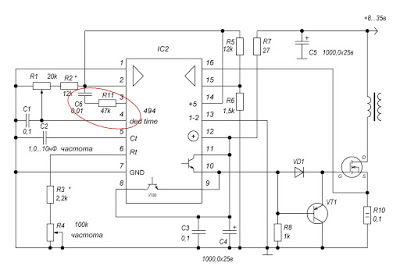
Single-cycle generator with adjustable frequency and sparing
A single-cycle generator with frequency and sparing regulation (adjustment of pulse tremor to pause treble). With one transistor output driver. Such a regime is realized, as if by joining the visnovok 13 from the living bus.
Scheme (1)
The oscillating microcircuit can have two output cascades, which in this case work in phase, you can turn on parallel to increase the output stream ... Otherwise, do not turn it on ... (green color on the diagram) Do not set resistor R7.
Vimiryuyuchi operational pіdsilyuvachem naprugu on resistor R10, you can obmezhite strum. The other input is supplied with a reference voltage by a dilator R5; R6. Well, you know, R10 will heat up.
Lanzug C6; R11, on (3) leg, set for greater stability, ask for the date, but work or without it. The transistor can take i npn structure.
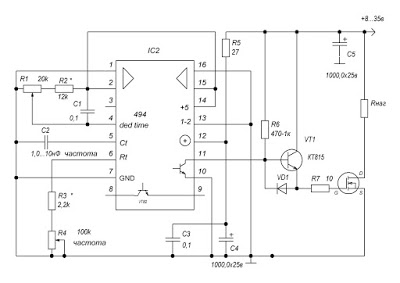
Scheme (2)
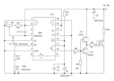
Scheme (3)
Single-cycle generator with frequency and spacing regulation. Three transistor output drivers (complementary repeater).
What can I say? The shape of the signal is better, transitional processes are short at the moment of switching, more navantage building, less heat consumption. Although it may be a subjective thought. Ale. At the same time, I have less than a two-transistor driver. So, the gate latch resistor is between the speed of transitional processes when switching.
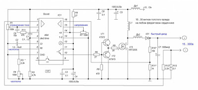
Scheme (4)
And here we can see the scheme of a typical booster (boost) of a regulated single-cycle switch, with the regulation of the voltage and the exchange of the stream.
The working scheme was chosen by me from a few vipads. Vih_dna napruga lie in the number of turns of the coil L1, and that in the support of the resistor R7; R10; R11, as if the hour of the day is getting better... You can wind the cat itself for whatever it is. Rozmir - fallow in the strain. Kіltse, Sh-core, just wind on the haircut. But it’s not her fault to go in to hell. To that, as a ring of ferrite, it is necessary to cut and glue it with a gap. Kindly send large circles of computer blocks of life, they do not need to be cut, the stench of the "sawed hall" clearance is already passed. As a W-like core - we put no magnetic gap, but with a short middle core - no longer with a gap. In short, let's go to the middle or mounting dart(0.5-1.0 mm in fallowness in tension) and the number of turns is 10-i more (fallow, as it is necessary to take the pressure off). It is connected to the planned pressure of a small strain. We connect our vitvir to the battery through a hard lamp. If the lamp did not burn out in the last fire - take a voltmeter and an oscilloscope.
Choose resistors R7; R10; R11 is the number of turns of the coil L1, depending on the intended voltage on the coil.
Throttle Dr1 - 5 ... 10 turns with a similar drotom on any core. Bachiv navit options, de L1 and Dr1 are wound on one core. I didn't check it myself.
Scheme (5)
Tsezh is a real reworking scheme, which is moving, which can be twisted, for example, for charging a laptop car battery. Input comparator (15); (16) follow the voltage of the "donor" battery and turn on the converter, if the voltage at the new input is lower than the specified threshold.
Lanzug C8; R12; VD2 - so the titles of Snubber, assignments for strangling inductive wikis. Ryatuє low-voltage MOSFET, for example, IRF3205 vitrimuє, so I don’t have mercy, (stik - vitik) up to 50v. Prote cool change KKD. I diode and resistor are decently heated. For those growing arrogance. In certain modes (schemes) without it, the strained transistor simply burns out. But it works without anything ... You need to marvel at the oscilloscope ...

Scheme (6)
Two-stroke generator, what do you ask.
Various options for vikonnannya and regulation.
At first glance, the majestic versatility of the inclusion schemes can be reduced to a richly modest number of practical practical ones ... First, I’m shy to sound, if I’m running a “cunning” scheme - the over-malicious standard for myself. Earlier it was called - GOST. At the same time, they didn’t realize how much it would make it easier to take it. I receive pardons. I think it's often necessary to do it on purpose.
Specifies a generator for a pivbridge or a bridge. The simplest generator, impulse response and frequency are manually adjusted. The optocoupler according to (3) nozі can also regulate the trivality, the proteoregulation is even worse. I am a recruiter for the revision of robotic microcircuits. Acts of the "luminaries" seem that it is not possible to control the (3) visnovka, the microcircuit will burn out, but I confirm the practicality of this decision. Before the speech, it was victorious in the distance in the brewing inverter.

Scheme (10)
Apply the implementation of the regulation (stabilization) of the struma and the voltage. Those who robbed little No. 12 himself - they deserved it. Blue capacitors, singsongly, can not be installed, but let them be better.

Scheme (11)
Generator on TL494 with adjustable frequency and sparring
Let's take a closer look for an hour of experimentation and tuning robots - a frequency generator. Vymogi schodo new small, more needed:
- frequency regulation (pulse forwarding period)
- regulation of spalling (coefficient of filling, duration of impulses)
- wide range
The frequency control range of the generator is superbly high - in tens of hertz up to 500 kHz, and in some ranges - up to 1 MHz, it can be found in a microcircuit, in other types of generators in different real values of the maximum frequency, as you can "change".

Let's move on to the description of the scheme:
Піт± и Піт~ - living digital part of the circuit, constant and changeable voltage, 16-20 volts.
Vout - the voltage of the power part, it will be at the output of the generator itself, 12 volts. In order to power the digital part of the voltage circuit, it is necessary to connect Vout and Pit± with polarity correction (output 16 volts).
OUT(+/D) - power output of the generator, polarity fixed. + - Plus life, D - drain field transistor. Prior to them, vanity is connected.
G D S - a screw block for connecting a field-effect transistor, which is chosen according to the parameters of the fallow, according to your needs, up to the frequency and tension. The opening of the other payment was made with the adjustment of the minimum allowance of conductors to the exit key and the required width.
Management bodies:
Rt is a variable resistor that controls the frequency range of the generator, it is necessary to select it according to your specific needs. The online calculator for the TL494 frequency rating can be found below. Resistor R2 surrounds the minimum value of the resistor support of the microcircuit. You can pick up a specific instance of the microcircuit, or you can put it like that on the diagram.
Ct - frequency-setting capacitor, power, again, up to online calculator. Allows you to set the range of regulation for your needs.
Rdt - changeable resistor for adjusting the spacing. Resistor R1 can accurately adjust the range of regulation from 1% to 99%, and you can also put a jumper on the back.
| Ct, nF: | |
| R2, com: | |
| Rt, com: |
Dekіlka slіv about the work of the scheme. By applying a low level of 13, the microcircuit (output control) won was transferred to single-cycle mode. The lower circuit transistor of the microcircuit is connected to the resistor R3 for turning the output for connecting to the frequency vibrating generator (frequency meter). The upper transistor of the microcircuit is driven by a driver on a complementary pair of transistors S8050 and S8550, which is controlled by a gate of a power output transistor. Resistor R5 surrounds the gate stream, its value can be changed. Choke L1 and capacitor єmnistyu 47n utvoryuyut filter for protection TL494 vіd possible shifts, created by the driver. Inductance of the inductor, it is possible, following the selection of the frequency range. It should be noted that the transistors of the S8050 and S8550 are not picked up badly, the stink shards can be sufficiently tight and firm to ensure the necessary coolness of the fronts. Yak bachite, the scheme is extremely simple, i, water hour, functional.
The replacement resistor Rt follows the viconate at the sight of two sequentially connected resistors - single-turn and multi-turn, as you need smoothness and accuracy of frequency regulation.
The board is crafted, following the tradition, painted with a felt-tip pen and stained with blue vitriol.
Like a power transistor, you can beat it practically be it field transistors, depending on the voltage, strum and frequency. May be: IRF530, IRF630, IRF640, IRF840.
The smaller the transistor opir at the work station, the less heat is needed for an hour of work. Tim is not less, the presence of the radiator on the new one is obov'yazkovoy.
It was chosen and twisted according to the scheme, like pressing the flyer.
CONTROL OF THE POWER KEYS OF THE IMPULSE LIFE UNIT
FOR AID TL494
THE ARTICLE IS PREPARED ON THE BASIS OF THE BOOK BY A. V. GOLOVKOV and V. B LYUBITSKY "FOOD UNITS FOR SYSTEM MODULES OF THE TYPE IBM PC-XT/AT"
CONTROL CHIP TL494
At modern DBZH for molding a keruyuchy spring, a switch tight transistors turn the sound of the victorious specialists integrated circuits(IMS).
The ideal IMC for ensuring the normal operation of the DBZH in the WIM mode is due to the satisfaction of the greater with the lowering of the minds:
operating voltage not higher than 40V;
the presence of a highly stable thermally stabilized reference voltage plug;
presence of a saw-type voltage generator
ensuring the possibility of synchronizing with a sound signal of a programmed soft start;
the presence of a signal of incompetence with a high common-mode voltage;
presence of the PWM comparator;
presence of a pulsed ceramic trigger;
the presence of a two-channel peredkіntse cascade from zahistomy in SC;
the presence of the logic of strangulation of the dependent impulse;
the presence of the means of correcting the symmetry of the output voltage;
presence of strum exchange in a wide range of in-phase voltage, as well as strum exchange in the skin period with switching on in emergency mode;
the presence of automatic transmission with direct transmission;
safe switching on when the voltage of life is reduced;
safety of zahistu from overexertion;
security of summ_snostі іz TTL/CMOS logic;
security of remote switching on and off.
Malyunok 11. TL494 microchip and pinout.
In the quality of the control circuit for the class of pulse blocks of life, which is considered, the microcircuit of the TL494CN type, which is produced by TEXAS INSTRUMENT (USA) (Fig. 11), is most important. It implements more of the listed functions and is issued on behalf of foreign companies under different names. For example, the SHARP company (Japan) produces the IR3M02 chip, the FAIRCHILD company (USA) - UA494, the SAMSUNG company (Korea) - KA7500, the FUJITSU company (Japan) - MB3759 and so on. All these microcircuits are the same analogues of the domestic microcircuit KR1114EU4. Let's take a look at the report and attach it to the robot with the help of a microchip. The wona is specially divided for the control of the power unit of the DBZh and for revenge at its warehouse (Fig. 12):
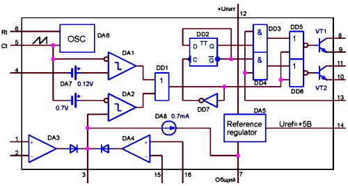
Figure 12. Functional diagram of ІС TL494
Generator saw-like voltage DA6; the frequency of the GPN is determined by the values of the resistor and capacitor, connected to the 5th and 6th turns, and in the BP class, which is viewed, is chosen equal to approximately 60 kHz;
dzherelo reference stabilized voltage DA5 (Uref=+5,OB) from outside output (visnovok 14);
comparator "dead zone" DA1;
PWM comparator DA2;
pіdsilyuvach pardon for the strain DA3;
pіdsilyuvach pardon signal zamezhennya strumu DA4;
two output transistors VT1 and VT2 with open collectors and emitters;
dynamic two-stroke D-trigger in the mode of rozpodіlu frequency by 2 - DD2;
additional logical elements DD1 (2-ABO), DD3 (2nd), DD4 (2nd), DD5 (2-ABO-NOT), DD6 (2-ABO-NOT), DD7 (NOT);
dzherelo constant voltage with a nominal value of 0.1BDA7;
dzherelo fast strumu with a nominal value of 0.7mA DA8.
The start-up control scheme, then. on 8 and 11 windrows, there are sequences of impulses in that fluctuation, as if on windings 12, if the voltage of life is given, the level of which is in the range of +7 to +40 V. The total number of functional units that enter the warehouse TL49, you can mentally break it down into digital and analog parts (digital and analog signal paths). Before the analog part, there are power switches DA3, DA4, comparators DA1, DA2, a sawtooth voltage generator DA6, as well as additional dzherel DA5, DA7, DA8. Usі іnshі elementi, zokrema i vihіdnі transistors, utvoryuyut digital part (digital path).
Figure 13. Robot ІС TL494 in nominal mode: U3, U4, U5 – voltages on ribs 3, 4, 5.
Let's look at the back of the robot's digital path. Timing diagrams, which explain the operation of the microcircuit, are shown in fig. 13. From the clock diagrams, it can be seen that the moments and appearance of the outgoing electric pulses of the microcircuit, as well as their trivality (diagrams 12 and 13) are assigned to the output of the logical element DD1 (diagram 5). Reshta "logic" vykonu only supplement the function of subdivision of output impulses DD1 on two channels. When the trivality of the output pulses of the microcircuit is determined by the trivality of the output of the output transistors VT1, VT2. So, since the obedience of the transistors can be connected to the collectors and the emitters, then it is possible to double the connection. When switched on behind the circuit from the main emitter, the output pulses are generated from the outer collector voltages of the transistors (from the 8th and 11th microcircuits), and the pulses themselves are directed downwards towards the positive level (the leading edges of the impulses are negative). The emitters of transistors (wires 9 and 10 microcircuits) at different times, sound, are grounded. When switched on behind the circuit with a hot collector, the calls are connected to the emitters of transistors and output impulses, straightened in the right direction by the impulses uphill (front front of the impulse is positive), they are connected to the transistors of the emitters VT1, VT2. The collectors of these transistors are connected to the microchip life bus (Upom).
The impulses of other functional nodes, which enter the warehouse of the digital part of the TL494 microcircuit, are directly connected by the wikis to the top, independently from the circuit of the microcircuit.
Trigger DD2 is a two-stroke dynamic D-trigger. The principle of yoga robotic axis y chomu. On the leading (positive) front of the output pulse of the element DD1, the input D of the trigger DD2 is written to the internal register. Physically, it means that the first of the two triggers is switched, which enters the warehouse DD2. If the pulse at the output of element DD1 ends, then the trailing (negative) edge of this pulse is switched by another trigger at warehouse DD2, and the output of DD2 is changed (on output Q, information is read from input D). This includes the possibility of appearing in the pulse on the basis of the skin transistors VT1, VT2, which last for one period. Indeed, as long as the pulse at the input of the trigger DD2 does not change, the output will not change. That impulse is transmitted to the output of the microcircuit via one of the channels, for example, the upper one (DD3, DD5, VT1). If the pulse at the input ends, the DD2 flip-flop switches, locks the upper and lower channel (DD4, DD6, VT2). That's when the impulse comes to go to the input and inputs DD5, DD6 will be transmitted to the output of the microcircuit via the lower channel. In this way, the skin of the outgoing impulses of the DD1 element with its negative edge peremikaє trigger DD2 and cym changes the channel of the advance impulse. Also, in the final material on the microcircuit, it is indicated that the architecture of the microcircuit ensures the suppression of the floating impulse, tobto. turns off the appearance of two pulses on the basis of one and the same transistor for the period.
Let's take a look at the report on the period of the robotic digital path of the microcircuit.
The appearance of a firing pulse on the basis of an output transistor of the upper (VT1) or lower (VT2) channel is determined by the logic of the robotic elements DD5, DD6 ("2ABO-NOT") and the camp of the elements DD3, DD4 ("2-I"), like, in its own line , is determined by the trigger mill DD2
The logic of the work of the 2-ABO element, as it seems, depends on the fact that the output of such an element is a voltage high level(logical 1) for that single input, as there are low equal voltages on both inputs (logical 0). For other possible combinations of input signals at the output of element 2 ABO-NOT present low voltage level (logic 0). Therefore, at the output Q of the flip-flop DD2 є logical 1 (moment ti in diagrams 5 in Fig. 13), and at the output / Q - logical 0, then at both inputs of the element DD3 (2I) logical 1 і appears, then, logical 1 appears on the output of DD3, also, on one of the inputs of the DD5 element (2ABO-NOT) of the upper channel. Later, regardless of the signal, which should go to another input of the element from the output of the element DD1, the output of the DD5 will be logical, and the transistor VT1 will be lost in the closed state. The output of the DD4 element will be logical 0, because logical 0 present in one of the inputs of DD4, suitable for the output /Q of the trigger DD2. The logical zero of the output of the element DD4 is located on one of the inputs of the element DD6 and ensures the possibility of passing the pulse through the lower channel. This pulse of positive polarity (logical 1) appears at the output DD6, and therefore on the basis of VT2 for an hour pause between the output pulses of the DD1 element (tobto for an hour, if at the output DD1 it is logical 0 - interval trt2 diagram 5 Fig. 13) . Therefore, the VT2 transistor turns on and the second collector is pulsed down as a positive level (at the time it is switched on behind the circuit from a bright emitter).
The ear of the offensive output pulse of the DD1 element (moment t2, diagrams 5 in Fig. 13) does not change the elements of the digital path of the microcircuit, the crim of the DD6 element, at the output of which a logical 0 appears, and therefore the transistor VT2 will close. The completion of the output pulse DD1 (moment ta) will zoom in on the output of the trigger DD2 on the length (logic 0 - on output Q, logical 1 - on output /Q). Therefore, the outputs of the elements DD3, DD4 will change (on the output DD3 - logical 0, on the output DD4 - logical 1). A pause that began at the moment! 3 at the output of the DD1 element to zoom in on the possibility of opening the transistor VT1 of the upper channel. Logical 0 on the output of the element DD3 "confirm" the possibility, transforming it into a real appearance of a pulse on the basis of the transistor VT1. This impulse lasts until the moment U, after which VT1 closes and the processes are repeated.
In this way, the main idea of the work of the digital path of the microcircuit is based on the fact that the trivality of the outgoing pulse on the windings 8 and 11 (or on the windings 9 and 10) is determined by the trivality of the pause between the outgoing impulses of the DD1 element. Elements DD3, DD4 assign the channel of passage of the impulse to a signal of low level, appearing to be drawn on the outputs Q і /Q of the flip-flop DD2, which is cured by the same element DD1. Elements DD5, DD6 are circuits for low level.
For a complete description of the functional capabilities of the microcircuit, we should designate one more feature. As can be seen from the functional diagram of the little one, the elements DD3, DD4 are combined and displayed on the 13th microcircuit. Since 13 visnovok is given logical 1, then the elements DD3, DD4 can be used as repeating information from the outputs Q і /Q of the trigger DD2. With this element DD5, DD6 i transistors VT1, VT2 will be zі zsuv in phase for half a period, ensuring the work of the power part of the DBZH, prompted by the two-cycle circuit of the bridge. If the logical 0 is given 13, then the elements DD3, DD4 will be blocked, so. stan vyhodіv tsikh elementіv nіchogo ochіkuvati zmіnyuvatisya (constant logical 0). Therefore, the output impulses of the DD1 element are the same on the DD5, DD6 elements. Elements DD5, DD6, also, and output transistors VT1, VT2, will be switched without phase loss (one hour). Such a mode of robotic microcircuits is reversed at times, as the power part of the DBZH is vikonan for a single-cycle circuit. The collectors and emitters of both output transistors and microcircuits in the same way are combined with the method of soothing.
Like "zhorstka" logical unity in two-stroke circuits, there is a victorious voltage
internal dzherel microcircuit Uref (visnovy 13 microcircuits are combined with views 14).
Now let's take a look at the analog path of the microcircuit.
The camp output DD1 is assigned to the output signal of the comparator PWM DA2 (diagram 4), which should be one of the inputs DD1. The output signal of the DA1 comparator (Diagram 2), which goes to another input of DD1, does not flow into the output of DD1 in normal operation, which is indicated by wider output pulses of the WIM - comparator DA2.
In addition, from the diagrams of Fig. 13 it can be seen that when the input voltage is changed, but not inverted, the PWM of the comparator (diagram 3) the width of the output pulses of the microcircuit (diagrams 12, 13) will change proportionally. In normal operation, the voltage level at the non-inverting input of the PWM comparator DA2 is only indicated by the output voltage of the DA3 break (because it outweighs the voltage of the DA4 switch), so that it is not equal to the reverse signal at the input input. 1 microcircuit). Therefore, when a signal of a turning signal is applied to the output of 1 microcircuit, the width of the outer switching impulses will change in proportion to the change in the signal of the turning signal, which, in its own right, will change proportionally zvorotny zvorotny zv'yazok start itself zvіdti.
Time intervals between the output pulses on the 8 and 11 microcircuits, if the output transistors VT1 and VT2 are closed, are called "dead zones".
The DA1 comparator is called the "dead zone" comparator, because Vіn vyznaє minimally possible її trivalіst. Let us explain the report.
From the timing diagrams in Fig. 13, it is clear that the width of the output pulses of the DA2 PWM computer will, for whatever reason, change, then gradually, due to the current width of the pulses of the output pulses of the DA1 comparator, they will become wider than the width of the PWM2-comparator to choose the output of the logical element DD1, also. the width of the output pulses of the microcircuit In other words, the comparator DA1 circles the width of the output pulses of the microcircuit at the first maximum level. The exchange rate is determined by the potential at the non-inventing input of the DA1 comparator (4 microcircuits are viewed) in the mode that it is installed. However, from the other side, the potential for output 4 is significant for the range of latitude regulation of the output pulses of the microcircuit. With an increase in the potential of the vysnovka 4, the whole range sounds. The widest range of regulation is available only if the potential for output is 4 or 0.
However, in this case, the fault is not safe, it is connected with it, that the width of the "dead zone" can be equal to 0 (for example, for a different increase in the stunted BDZh strum). Tse means that the key impulses on the 8 and 11 microcircuits follow without interruption one by one. The situation can be blamed for this, I’ll call it “a breakdown in accordance with the law”. It is explained by the inertia of the power transistors of the inverter, which can vibrate and curl up. That is, if one hour at the base of the closed transistor, apply a flickering signal, and to the base of the closed transistor - an unlocking signal (that is, with a zero "dead zone"), then we will see the situation, if one transistor has not yet closed, and the other is already closed. Todі i vinikaє probіy on the transistor stіytsі napіvmostu, which polagáє at protіkannі sryznі strumu through the transistor's edge. Strum tsey, as can be seen from the scheme of fig. 5, mine is the primary winding of the power transformer and there are practically no surroundings. Zakhist strumu is not practiced at times, because The strum does not flow through the streak sensor (there are no indications on the diagram; the design and principle of stopping streak sensors will be reviewed in the upcoming sections), which means that this sensor cannot see a signal to the control circuit. Therefore, the nasty strum reaches great magnitude in just a short span of an hour. It is necessary to produce to a sharp increase in tension, which is seen on both power transistors, and a practical mitt out of the way (as a rule, a break). In addition, the throw of a cracked struma can be brought out of the fret of the diode of the power bridge, which is straightened. This process ends with the burnout of the treadmill, which, through its inertia, does not grasp the elements of the scheme, but rather protects the first treadmill.
Tom strong voltage; filed on the basis of power transistors can be molded in such a way that one of these transistors is suddenly curled up, and then the other one is broken. In other words, between the critical pulses that are fed to the base of the power transistors, the clock sound is not equal to zero ("dead zone"). The minimum allowable "dead zone" trivality is determined by the inertia of stasis as a power switch of transistors.
The architecture of the microcircuit allows you to regulate the value of the minimum tremor of the "dead zone" for the additional potential of the 4 microcircuit. The potential of this function is for the help of the old timer, which is connected to the output voltage bus of the internal reference voltage of the Uref microcircuit.
Some variants of the DBZH have such a dilnik every day. Tse means that after the completion of the soft start process (div. below), the potential for displaying 4 microcircuits becomes equal to 0. 1B), which is connected to the non-inverting input of the comparator DA1 with its positive pole, and the connection 4 of the microcircuit is negative. In this way, the width of the outgoing pulse of the comparator DA1, and therefore the width of the "dead zone", for everyday minds cannot be equal to 0, and it means "breakdown according to the station" will be impossibly. In other words, the microcircuit architecture is based on the exchange of the maximum trivality of the output pulse (minimum trivality of the "dead zone"). Yakschko є Dial, pіdlisii to Vyprennya 4 mіkrosshemi, then pіsl smooth start by the potential of the Central Villode does not dor_vnyuє 0, the width of the swirl ipulsіv comparator DA1 promptly not t_lki internal jerell DA7, and y Zalishkov (pіsl completed the process of smooth launch) at Vyovylannі 4. Therefore, as it was assigned more, the dynamic range of the width regulation of the PWM comparator DA2 sounds.
START-UP SCHEME
The start-up circuit is recognized for voltage reduction, which can be used to power the power microcircuit with the method of starting after the ball screw is turned on in the live life. Therefore, before the start-up, it may be necessary to launch the robot in the first line of a critical microcircuit;
The launch scheme can be induced in two different ways:
from self-excitement;
from primus zbudzhennyam.
The scheme of self-excitation is victorious, for example, in the GT-150W DBZH (Fig. 14). The rectified voltage Uep is applied to the resistive resistor R5, R3, R6, R4, which is the base for both key power transistors Q1, Q2. Therefore, through the transistors under the influx of the total voltage on the capacitors C5, C6 (Uep) basic strum lanzug (+) C5 - R5 - R7 - 6th Q1 - R6 - R8 - 6th Q2 - "fire wire" of the primary side - (-) C6.
Offending transistors with a strum. As a result, through the collector-emitter boards, both transistors are repaired by flowing streams of mutually opposite direct lines along the lances:
through Q1: (+) C5 - +310 V bus - to-e Q1 - 5-6 T1 -1-2 T2-C9- (-) C5.
through Q2: (+) C6 - C9 - 2-1 T2 - 6-5 T1 - to-e Q2 - "fire wire" of the primary side - (-) C6.
Malyunok 14. Scheme for launching the DBZh GT-150W from self-excitation.
Yakby obidva strum, which flow through the additional (starting) turns 5-6 T1 at the opposite straight lines, were equal, then the resulting strum would reach 0, and the circuit would not be able to start.
Prote z tekhnologicheskogo rozkidu koefіtsієntіv strimy strumu transistors Q1, Q2 transistors for different world. Therefore, the resulting strum through turns 5-6 T1 is not good for 0 and may be the other way. Let's assume that the stream passes through the transistor Q1 (that is, Q1 is open to the greater world, lower Q2) and, then, the stream flows from the front of the output 5 to the output of 6 T1. Further mirkuvannya are grounded on whom the allowance is.
However, for the sake of fairness, it should be noted that it is more important that the stream through the transistor Q2 is more important, and then all the described processes will be placed before the transistor Q2.
The passage of the struma through the turns 5-6 T1 causes the EPC to reverse the mutual induction on all windings of the T1 electric transformer. With this (+) EPC blamed on the visnovka 4 shodo 5 i into the base Q1 under the inflow of the tsієї EPC flow dodatkovo strum, which yogo v_dkrivaє along the lancet: 4 T1 - D7-R9-R7-6-3 Q1 - 5 T1.
One hour at the 7 T1 show (-) EPC is about to show 8, tobto. the polarity of the EPC circuit appears to be locking Q2 and VIN is closed. Dalі nabuvaє chivalry positive zvorotny zv'azok (POS). The difference lies in the fact that when the stream grows through the lot of the collector-emitter Q1 and turns 5-6 T1 on the winding 4-5 T1, the growth of the EPC, yak, creating an additional base stream for Q1, is a bigger world in the yogo. The process develops like an avalanche (arguably fast) and leads to a complete recurrence of Q1 and a decrease in Q2. Through the voltage of Q1 and the primary winding 1-2 of the power pulse transformer T2, the strum starts to flow, which grows linearly, which calls out the appearance of an EPC pulse in mutual induction on all windings of T2. Impulse from the windings 7-5 T2 charges the accumulative capacity C22. A voltage is applied to C22, as it is fed like a revitalizer to the 12-ring IC1 microcircuit of the TL494 type and to the cascade. The microcircuit starts up and generates on its own circuits 11, 8 straight-line sequences of pulses, which, through the cascade (Q3, Q4, T1), begin to remerge the power switches Q1, Q2. On all windings of the power transformer T2, the EPC impulses of the nominal level are vibrated. At the same ERS of windings 3-5 and 7-5, they constantly increase C22, while at the same time they increase the constant voltage level (close to + 27V). In other words, the microcircuit begins to inspire itself (self-sustaining) according to the ring of the virtuous link. The block enters the operating mode. The voltage of life of the microcircuit and the narrow cascade is additional, only in the middle of the block and the sound is called Upom.
This circuit can be used differently, as, for example, in the LPS-02-150XT impulse block (Taiwan manufacturing) for the Mazovia SM1914 computer (Fig. 15). In this scheme, the cob post for the development of the launch process should go for the help of a one-pv-period straightener D1, C7, which feeds the first positive pvp period of the base line for power switches, a resistive dilnik. Tse speed up the launch, because firstly, one of the keys is connected in parallel with the charging of smoothing capacitors in a large capacity. Otherwise, the scheme works in the same way as before.

Figure 15. Scheme of starting from self-excitation in the pulse block of life LPS-02-150XT
Such a scheme is victorious, for example, in the PS-200B DBZH of the LING YIN GROUP company (Taiwan).
The primary winding of the special starting transformer T1 is switched on at half voltage (at nominal 220V) or at full voltage (at nominal 110V). Tse to work quietly, so that the amplitude of the variable voltage on the secondary winding T1 does not lie with the rating of the life line. Through the primary winding T1, when the DBZH is on, it flows through the change strum. On the secondary winding 3-4 T1, a variable sinusoidal EPC with the frequency of the life line is induced. The strum, which flows under the inflow of EPC lines, is rectified by a special bridge circuit on diodes D3-D6 and is smoothed out by capacitor C26. On C26, a constant voltage is seen close to 10-11V, as it is fed like a life-giving 12 microcircuit U1 type TL494 and to the cascade. In parallel with this process, the charge of the filter capacitors is charged, which is smoothed out. Therefore, at the time of feeding the food to the microcircuit, the power cascade also appears to be powered. The microcircuit starts up and starts generating on its own circuits 8, 11 sequences of rectilinear impulses, like through a cascade, which are necessary, start switching power keys. As a result, the output voltages of the block are declared. After entering the self-sustaining mode of the microcircuit, it is carried out from the output voltage bus + 12V through the diode D8, which is connected. So, as the voltage of the self-sustaining voltage of the troch overrides the voltage of the D3-D5 retractor, the diodes of the starting retractor flicker, and the voltage does not flow into the operation of the circuit.
The need for a salutary connection through the diode D8 is not binding. In the schemes of some BDZH, de zastosovuetsya primus damage, such a link every day. The power microcircuit and the narrow cascade, for a short time, the robots are powered from the output of the starting vibrator. However, the pulsation rate on the Upom bus in this case is usually larger, lower in the development of the microcircuit from the output voltage bus + 12V.
Summing up the description of the launch schemes, you can name the main features of their motivation. In the self-excitation circuit, an alternation of power transistors is carried out, resulting in the appearance of a voltage of the Upom microcircuit. In the circuit with primal priming, Upom is removed, and as a result, the switching of power transistors. In addition, in circuits with self-excitation, the voltage Upom sound may be close to + 26V, and in circuits with primary priming, it is close to + 12V.
The circuit with primus zbudzhennyam (with a transformer) is shown in Fig. 16.
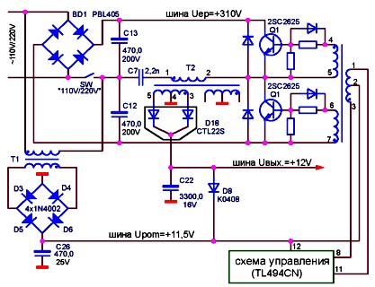
Figure 16 impulse block living PS-200B (LING YIN GROUP).
PLEASANT CASCADE OF THE IMPULSE LIFE UNIT
For uzgodzhennya that rozvyazki natuzhnogo vykhіdnogo cascade in vіd low-pressure lanceugіv management serve uzgodzhuychiy cascade.
Practical schemes for inducing a narrow cascade in various BDZh can be divided into two main options:
transistor variant, de yak keys vikoristovuyutsya zovnіshnі transistors in a discrete vikonannі;
non-transistor variant, de-yak the keys are switched out of the transistors of the most important microcircuit VT1, VT2 (in the integrated circuit).
In addition, another sign, for which it is possible to classify narrow cascades, is a way of managing power transistors nap_bridge inverter. For this sign, all the uzgodzhuvalny cascades can be subdivided into:
cascades from overhead controls, de control of both power transistors, are carried out behind the help of a single transformer that is critical for them, which has one primary and two secondary windings;
cascades with separate controls, decoupling the skin from power transistors vibrate with the help of a nearby transformer, that is. The weather cascade has two control transformers.
Vikhodyachi s both classifications narrow cascade can be vikonanie one of the following ways:
transistorized from overhead controls;
transistorized from separate controls;
transistorless from overhead controls;
transistorless from separate controls.
Transistor cascades with separate controls are rarely switched, otherwise they are not switched. The authors did not have a chance to close the cascade with such an option. The other three options appear more and less often.
In all modes, connections from the power cascade are made by the transformer method.
With this transformer, there are two main functions: strengthening the strum signal (for weakening the voltage) and galvanic decoupling. Galvanic decoupling is necessary for the fact that the power circuit and the cascade, which can be used, are on the secondary side, and the power cascade is on the primary side of the DBZH.
Let's take a look at the work of the dermal detection of options for the narrow cascade on specific butts.
In the transistor circuit from the upper controls, as a narrow cascade, there is a two-stroke transformer front pressure suppressor on transistors Q3 and Q4 (Fig. 17).
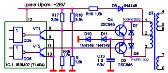
Figure 17. Weather cascade of the KYP-150W pulsed power unit ( transistor circuit from the upper management).

Figure 18. Actual shape of pulses on collectors
Strumi through the diodes D7 and D9, which flow under the influx of magnetic energy stored in the DT core, may look like exponents, which will subside. At the DT core, the flow of strums through the diodes D7 and D9 has a variable (decreasing) magnetic flux, which causes the appearance of EPC pulses on yoga secondary windings.
Diode D8 is used by injecting the cascade onto a power microcircuit through a power bus.
The second variety of the transistor narrow cascade from the top controls is played in the ESAN ESP-1003R pulsed power supply (Fig. 19). The first special feature of this option is those that use transistors VT1, VT2 of the microcircuit to turn on as an emitter repeater. Output signals are taken from 9 circuits, 10 microcircuits. Resistors R17, R16 і R15, R14 are em-terminated transistors VT1 and VT2, obviously. These resistors are used as basic switches for transistors Q3, Q4, as they work in the key mode. Capacities C13 and C12 are forcing and accelerating the processes of switching transistors Q3, Q4. Other characteristic feature th cascade and those that the primary winding of the core transformer DT does not have a connection to the middle point and is connected between the collectors of transistors Q3, Q4. If the output transistor VT1 of the microcircuit is turned on, then the voltage Upom is used as the base for the transistor Q3 dilnik R17, R16. Therefore, a strum flows through the key transition Q3 and the veins break. Accelerating this process, forcing the capacity of C13, so as to ensure the supply of strum to the Q3 base, which shows that the value has changed by 2-2.5 times. The result of the Q3 opening is those that the primary winding 1-2 DT is connected to the case to its own appearance. So like another transistor Q4 circuits, then through the primary winding DT, the strum starts to flow, which grows, according to the lance: Upom - R11 - 2-1 DT - up to Q3 - case.
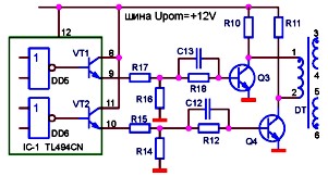
Figure 19. ESP-1003R ESP-1003R ESAN ELECTRONIC CO., LTD.
On the secondary windings 3-4 and 5-6 DT, EPC pulses of a rectangular shape are applied. Direct winding of secondary windings DT different. Therefore, one of the power transistors (not shown in the diagram) takes the base impulse, which turns the curve, and the other one closes the curve. If VT1 of the particular microcircuit closes sharply, then Q3 also closes sharply after it. Accelerating the curing process, the forcing capacitance of C13 is applied, the voltage is applied before the Q3 base-emitter transition in polarity, which closes. Dali trivaє "dead zone", if the offending transistors of the microcircuit are closed. Next, the output transistor VT2 turns on, and it also turns on the supply voltage Upom to the base of another transistor Q4, R15, R14. To that Q4 turns and the primary winding 1-2 DT appears to be connected to the body with its other end (visnovka 2), to that, through it, an increasing stream of the prolonging frontal fall straight along the lance begins to flow: Upom -R10- 1-2 DT - to-e Q4 - "frame".
Therefore, the polarity of the impulses on the secondary windings of DT changes, and that the impulse curve takes another power transistor, but in the basis of the first impulse, the polarity curve closes. If VT2 of the critical microcircuit closes sharply, then Q4 also closes sharply behind it (for the additional booster capacity C12). We gave a new "dead zone", after which the processes are repeated.
In this way, the main idea is embedded in the work of this cascade, which is based on the fact that the significant magnetic flux at the DT core is allowed to take into account the fact that the primary winding DT is connected to the case with one, then with its other end. That is why a change stream flows through it without a permanent warehouse with a unipolar life.
In non-transistor variants of the narrow cascades of the DBZH, like transistors in the narrow cascade, as it was indicated earlier, the transistors VT1, VT2 are switched out of the microcircuit. In this way, discrete transistors of the narrow cascade are available.
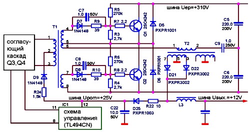
The transistorless circuit from the top controls is victorious, for example, in the PS-200V DBZH circuit. The output transistors of the microcircuit VT1, VT2 are wound by the collectors with the first windings of the transformer DT (Fig. 20). Life is supplied to the midpoint of the primary winding DT.

Figure 20. Weather cascade of the PS-200B pulsed power supply (transistorless circuit with hot circuits).
If the transistor VT1 turns on, then the stream, which grows, flows through the entire transistor and winding 1-2 of the DT transformer. On the secondary windings of DT, there are some pulses that cause such polarity, that one of the power transistors of the inverter turns on, and the other one closes. After the end of the VT1 pulse, it sharply closes, the jet through the winding 1-2 DT stops flowing, this causes EPC on the secondary windings of DT, which causes the power transistors to close. Dali trivaє "dead zone", if the offending transistors VT1, VT2 of the microcircuit are closed, and the stream does not flow through the primary winding DT. Farther, the transistor VT2, strum, accelerating in the hour, flows through the entire transistor and winding 2-3 DT. The magnetic flux, created by the cym strum at the DT core, may be straight forward in the direction of the front. Therefore, on the secondary windings DT, EPCs are induced in the opposite direction of the forward polarity. As a result, another transistor of the napbridge inverter is turned on, and on the basis of the first pulse, the second polarity can be turned off. If VT2 of the microcircuit is closed, the strum is connected through the new and primary winding DT. Therefore, EPC on the secondary windings DT, and the power transistors of the inverter are closed again. We gave a new "dead zone", after which the processes are repeated.
The main idea of encouraging the cascade is that the change in the magnetic flux in the core of the transformer, which is controlled, should be taken into account to feed the food into the middle point of the primary winding of the transformer. That is why streams flow through the windings with the same number of turns in different straights. If the offending transistors of the microcircuit are closed ("dead zones"), the magnetic flux at the DT core is fine. The resulting magnetic flux at the core will change.
The rest of the designations of the different types (transistorless circuit with separate controls) are victorious, for example, in the DBZh of the Appis computer (Peru). This circuit has two control transformers DT1, DT2, the primary windings of which are collector windings for the output transistors of the microcircuit (Fig. 21). In this circuit, skin protection from two power switches is carried out through an silicon transformer. Live power is supplied to the collectors of the output transistors of the microcircuit from the Upom bus through the midpoints of the primary windings of the control transformers DT1, DT2.
Diodes D9, D10 with the main parts of the primary windings DT1, DT2 establish demagnetization circuits of the cores. Let's get down to what nutritional report.
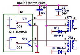
Figure 21. Weather cascade of the "Appis" pulsed power supply (transistorless circuit with separate controls).
The narrow cascade (Fig. 21) is actually two independent single-stroke straight-running reversals, because v_dkrivaє strum protіkaє the basis of the power transistor pіd hour vіdkritogo I will become an uzgodzhuvalny transistor, tobto. Uzgodzhuyuchiy that pov'yazany z him through the transformer power transistor vіdkritі one hour. When you feel offended pulse transformer DT1, DT2 are processed from a permanent storage jet of the primary winding, that is. z vimushenim pіdmagnіchuvannyam. If you don’t transfer special inputs from the remagnetization of the cores, then you will see the stench of the magnetic force for a few periods of work, which will lead to a significant change in the inductance of the primary windings and the exit from the fret of the transistors VT1, VT2, which will jump. Let's take a look at the processes that transform on transistors VT1 and transformers DT1. If the transistor VT1 turns on, through the new and primary winding 1-2 DT1 a stream flows, which grows linearly, along the lance: Upom -2-1 DT1 - to-e VT1 - "body".
If the unlocking impulse with the VT1 leveling up ends, the vent closes sharply. The jet through the winding 1-2 DT1 is attached. However, the EPC on the winding 2-3 DT1 with the change of polarity, and through the winding and the diode D10, the demagnetizing core DT1 flows along the lance: 2 DT1 - Upom - C9 - "case" - D10-3DT1.
Strum tsey - linearly falling, tobto. similar to the magnetic flux through the core DT1 changes the sign, and the core is demagnetized. In this way, under an hour of the turning cycle, the excess energy stored in the core DT1 per hour of the turned-on transistor VT1 is turned into a dzherelo (the accumulative capacitor C9 of the Upom bus is charged).
However, such a variant of the implementation of the cascade, whatever the weather, is the least important, because Transformers DT1, DT2 are operated with undervoltage by induction and with a permanent storage jet of the primary winding. The remagnetization of the cores DT1, DT2 follows a private cycle, which only positively values the induction. The magnetic fluxes in the hearts through the chain appear pulsating, tobto. avenge the post warehouse. It is necessary to produce up to the dependence of the weight and size indicators of transformers DT1, DT2 and, moreover, in pairs with other variants of the narrow cascade, here two transformers are needed instead of one.
| BASIC PARAMETERS OF LIFE PULSE UNITS FOR IBM | The main parameters of the impulse blocks of life are examined, the pinning of the rose is made, the principle of operation in the voltage of the wire is 110 and 220 volts, | |||
| The TL494 microcircuit is described in detail, the circuit for switching on and variant of the switch for the power keys of the pulse blocks of life. | ||||
| CONTROL OF THE POWER KEYS OF THE IMPULSE UNIT FOR AID TL494 | The main methods of controlling the base switches of power transistors in pulsed life blocks, options for inducing secondary life are described. | New description principle diagram that її work of the impulse block of life | ||


