Linear stabilizer 5 tbsp. Do-it-yourself voltage stabilizer circuits
All good new holidays!
A long time ago, if they discussed where the voltages are in the living sensors in the ECU, I suggested that a stabilizer be used for 5v and plug in the new sensors.
Know the scheme of the stabilizer, having purchased components and soldered it. Please consult with McSystem in advance.
Stabilizer scheme:
Ic1 - stabilizer 7805 (import substitution KREN5). It’s safe that 7805 is very strong and needs to work with the simplest filters with ceramic capacitors at the input and output:
Analogues: LT1083, LT1084 - more efficient and accurate stabilizers. And ideally - especially for the ECU assignments TLE 4267.
LM317 - Vіn accepting and stable and allows you to accurately apply the voltage.
R1 - 10-20 Ohm resistor for additive filtering.
C1 - polar electrolytic capacitor with a capacity of 100mKf 16v. The minimum parameters of the capacitor can be taken with a larger capacitance, but not more than 25v.
C2 - ceramic capacitor with a capacity of 0.33 microfarads. The minimum capacitance of such a capacitor can be 0.22 microfarads.
C3 - ceramic capacitor with a capacity of 0.1mKf.
C4 - polar electrolytic capacitor with a capacity of 680mKf 6.3v. The place can be taken another way, but not varto zbіshuvati or change the voltage.
Ideally, the replacement of ceramics is better than tantalum capacitors, which will be more important for the stabilization of the struma.
Slept on the mounting plate. I have lost the relay case, which I pulled out of the coil for experiments. The payment was broken, so that it could fit in the relay case.

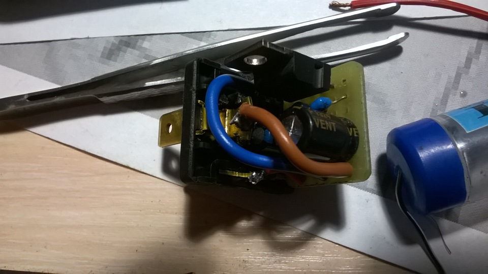
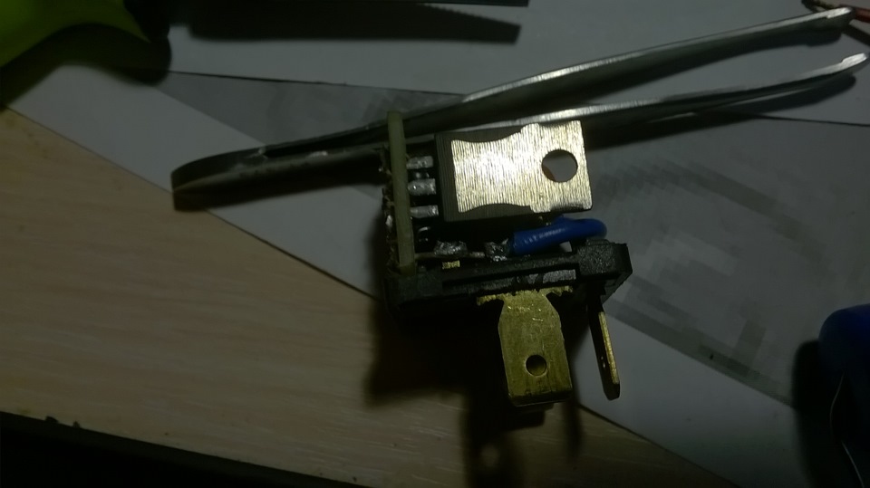
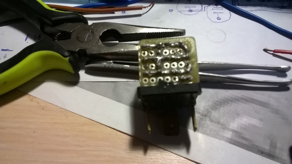

The relay contacts were interfering with the attacking functions: 85 leg - stabilizer life +12v, 86 leg - weight, 87 leg - out +5v.
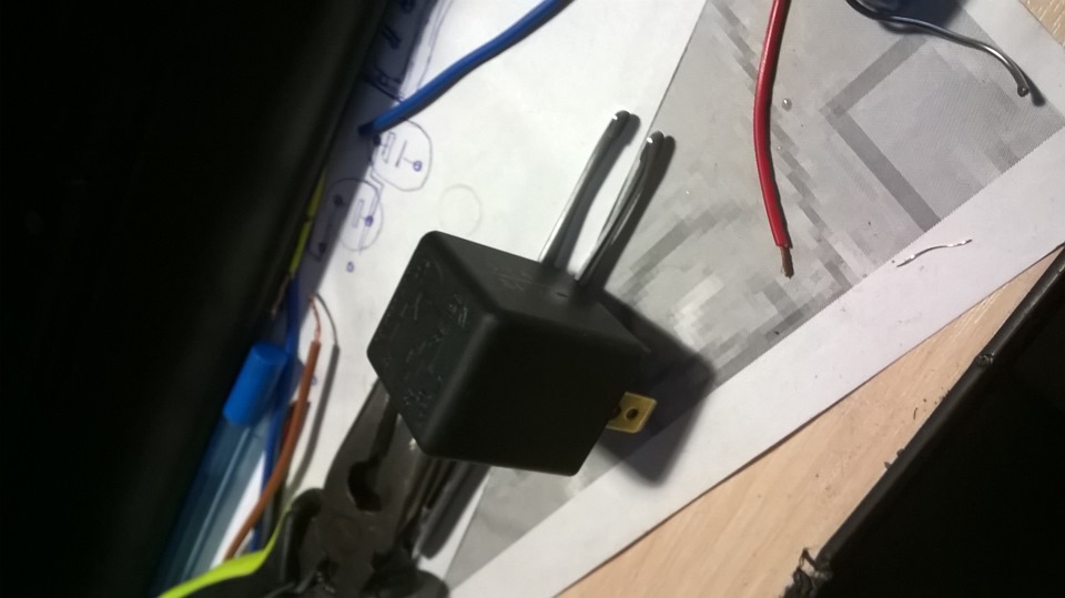
Potisti vіd blocіv zhivlennya. for +13.2v it is 4.94v, for +12v out 4.94v, for +11v out 4.94v.
It has been lost to put a stabilizer at the lancets of live sensors, tobto. open the wire of the ECU and compress it with clamps, so that the stabilizer can be taken out or put in.
Still, I don’t need a stabilizer based on 7805, I’m going to use LM317 and a little extra circuit, which will be stronger than 7805.
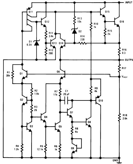
This small article is dedicated to the trivivid stabilizer springs L7805. The microcircuit is produced in two types, in plastic - TO-220 and metal - TO-3. Three visnovki, marveling levoruch pravoruch - introduction, minus, exit.
The remaining two digits indicate a stabilized voltage microcircuits- 7805-5 volts, 7806-6v...
Axis connection diagram stabilizer how to fit for all microcircuits of this series:

We don’t marvel at small-capacitance capacitors, it’s better to put a larger yakomog.
Well, what about the stabilizer in the middle:
Wow, right? And everything is placed ... A miracle of technology.
Otzhe, we tsіkavlyat і characteristics. output voltage - output voltage. Input voltage - input voltage. Shukaєmo our 7805. Vіn vidє vіdnu vihіdnu prugu 5 volts. Bagan input voltage virobniki indicated a voltage of 10 volts. Ale, it’s so, that the voltage is stabilized, sometimes it’s either underestimated, or it’s protected by a little. For electronic devices, often volts are not observed, but for precision (accurate) equipment, it’s better to choose your own circuits. Here we can see that the stabilizer 7805 can see one of the voltage range of 4.75 - 5.25 Volts, but if you do this, you need to trim the minds (conditions), so the stream at the exit in the voltage does not exceed one Ampere. Unstabilized constant voltage can "hit" in the range from 7.5 to 20 volts, with which the output will be 5 volts. Tsomu has a great plus of stabilizers.
With a great desire, and this microcircuit is designed to give an intensity of as much as 15 watts, it is better to provide a radiator and, if possible, or for the air, for greater that dry cooling, screw your cooler like a computer.
Axis i normal scheme of the stabilizer:

Technical characteristics
Housing...to-220
Maximum strum navantazhennya, ... 1.5
Permissible input voltage range, V... 40
Output voltage, V... 5
to help.
In order for the stabilizer not to overheat, it is necessary to increase the required minimum voltage at the input of the microcircuit, so that we have the L7805, then 7-8 volts are allowed at the input, which is 12 - 14-15 volts.
Tse pov'yazano z scho, scho overworld tension stabilizer rossiyuvateme on yourself. As you remember, the formula for tension is P = IU, de U is the tension, and I is the force of the struma. Also, the greater the input voltage of the stabilizer, the greater the tightness fit into it. And supra-mundane sweating - tse and є heating. As a result of heating, such a stabilizer can overheat and go into the camp of a defender, when the stabilizer works further away.
Voltage stabilizer for 5 volts, about which pide in this stat, can stop short flickers. Vіn appointments for living circuits with microcontrollers for the hour of their development. Stabilizer of insurance for installation on a solderless breadboard. Low pressure stabilizer that may have a maximum current surge of 0.15A. The development of a small and simple scheme was embarrassed by the controller's vigor during the experiments. Tsya scheme є supplemented to laboratory block eating. The scheme of the stabilizer is shown in small 1.
The basis of the circuit is a microcircuit, unfairly forgotten and the road, K157HP2, Before the warehouse to enter the voltage stabilizer with the on/off function. Tse 14 visible microcircuit, recognized for the use of magnetic recording equipment. And so the scheme works in such a way. When applying live to the output 10 of the DA1 stabilizer through the cooling diode VD1 with a Schottky barrier, voltage is applied. Vihіdna napruga z'appear only in that fluctuation, yakscho on vysnovok 9 DA1 file a positive voltage of at least two volts. At the first moment, the voltage, which is turned on, is formed by the lance R1 and capacitor C2, while the charge flows through. For an hour, the output of the stabilizer is 5 volts, part of which is through a resistor zvorotny zv'azku R2 is also fed to 9 DA1. This voltage, which is reduced, is necessary for the normal operation of the stabilizer. For the convenience of work with this prefix, two buttons are introduced into the circuit, for the help of which you can quickly switch on and off the voltage of the tested circuit. When pressing the Stop button, vysnovok 9 DA1 is shunted to the hot dryer - the stabilizer vibrates, which causes a voltage, which excites. When the button is released, the stabilizer will be left in a closed station, because the capacitor C2 is already charged fast strumu yoga opir is great. Those same vydbuvatimetsya and for the mind, if the stabilizer is out of the mode short hum. Tobto. the voltage is lost and the stabilizer is weak. And so, the stabilizer is located at the switched-off station, for it to be turned on, it is necessary to press the Start button. When I switch to 9 DA1, I renew the voltage, which is shown, through the button and the resistor R1, the stabilizer turns on. When this button is pressed, the voltage to support the stabilizer's operating mode will be supplied through the resistor R2.
The diagram does not show the output capacitors of the filter. If in the test circuit, the input capacitors are present according to the life, they should not be installed, but if they are not, then shunt the output of this stabilizer with a ceramic capacitor with a capacity of 0.1 and an electrolytic capacitor with a capacity of 0.1 ... 100.0 ... 100.0 ... 10 volts. Visnovok 8 microcircuit tse vihіd dzherela reference voltage of 1.3 volts. Capacitor C3 is a filtering one, at this hour in the first place, the hour of the stabilizer is turned on. For our mind, the capacity indicated on the scheme is sufficient. Resistor R4 to serve for p_dstroyuvannya output voltage. In principle, with such success, you can change the output voltage and for the additional resistor R3. I have a pickup stabilizer without any intermediary on the breadboard, but I would like my mother to get a hustka, like that, I wrote about yak in the article
Pidbirka radioamatorsky schemes and designs of voltage stabilizers chosen with their own hands. Part of the circuits is examined by a stabilizer without protection from short circuits at the input, in others, the possibility of smooth regulation of the voltage from 0 to 20 Volts is laid. well and homemade rice For okremih schemes є mozhlivіst zahistu vіd short zamikannya in vantagenni.
5 arcs simple circuits mainly selected on transistors, one of them is a short circuit
Even more often, if a stable voltage is needed for the life of your new electronic self-reliance, it does not change the type of voltage, for example, 5 Volts or 12 Volts for the life of the car radio. I don’t bother too much with the design of a self-contained block of life on transistors, so called voltage stabilizer microcircuits. At the exit of such an element, we take the voltage, on the basis of which this accessory is designed
Many radioamators have already repeatedly selected voltage stabilizer circuits on special microcircuits of the 78xx, 78Mxx, 78Lxx series. For example, on the KIA7805 microcircuit, you can select self-made scheme I’m insuranceed for a free voltage of +5 V and the maximum surge voltage is 1 A. Ale, few people know that it’s highly specialized microcircuits of the 78Rxx series, so you need to take into account the voltage stabilizers of positive polarity with low voltage, because the voltage is not shifted, 1 A. One of these schemes will be reviewed in the report.
Regulation trivivid positive voltage stabilizer LM317 safe stream voltage 100 mA in the range of output voltage from 1.2 to 37 V. In addition, the instability due to the voltage and strum of the stress in the stabilizer LM317L may have better indicators, lower in traditional stabilizers with fixing the values of the output voltage.
To stabilize the voltage of the steady strum, to increase the pressure of the middle ones, the compensatory stabilizers of the uninterrupted action are installed. The principle of operation of such a stabilizer affects the reduction of the output voltage at a given level for the change in the voltage drop on the regulating element. When the value of the keruyuchy signal, which should be on the regulating element, lie in the difference between the specified and output voltage of the stabilizer.
In the stationary operation of equipment, CD and audio players, problems with the power supply are blamed. Most blocks of life, which are issued serially by a virobnik, (as well as being accurate) practically can not please all the living, shards to avenge the simple schemes. If you talk about imported Chinese and similar food blocks, then the stench, vzagali, represent a collection of details "buy and win". Numbers and a lot of other problems zmushuyut radioamatorno vygotovlyat blocks of life. But at this stage, amateurs are stuck with the problem of choice: the design is published without a face, but not all is well practiced. This radioamator's report is presented as a variant of the non-traditional inclusion of an operative patient, previously published and unintentionally forgotten
May all radioamator's self-confidences and designs may have stabilized life in their warehouse. And if your design is based on the voltage of five volts, then best option will be trivivid integrated stabilizer 78L05
Voltage stabilizer for 220 volts |


