Transistor stabilitron. Napіvprovіdnikovі analogues stabilіtronіv. An analogue of a strain-fitting zener diode as a test drive for re-verification of chargers in car batteries
When converting computer pulse blocks of life (further - DBZH) for charging attachments car batteries, get ready to choose what you need to nawantage. The back of the head is old battery for battery with car lamp 12V 40/45W.
The reworking of DBZH was trimmed under the maximum stress of the day. Ale, after the preparation of the tenth, I will attach the battery to the dead, they closed the plates between themselves. Trying to navantage the DBZH with hard lamps or resistors did not please, because when different strums the effort at the exit is taken away from the pressure, it is not easy to adjust the DBZH.
Like a transistor vikoristovuetsya with yogo basic pink circuit, the collector path to the emitter is like a stabilitron, conducting sequentially with a sig- nificant diode. In this way, if the base stream is equal to zero, the transistor passes only a small stream of a turn. If the collector voltage exceeds hundreds of millivolts, the collector streak may be directly proportional to the base streaks, it is not enough to lie due to the collector voltage value.
In this rank, attachments can be victorious like a generator fast strumu way to supply a fixed stream of sound to the base, or it can be victorious as a linear subsidy by way of imposing an input signal on a nominal input stream. The transistor can be found in different configurations of the basic circuit, and part of the cob episode that is missing is a short look the most important of them.
Therefore, it was decided to prepare an analogue straining zener diode with regulated voltage stabilization!
Scheme and design description

Resistor R6 can regulate the stabilization voltage from 6 to 16 St.
Bulo prepared two such outbuildings. In the first variant, like transistors VT1 and VT2, the KT803 was blocked, but the internal opir was too large, so with a stream of 2 A, the stabilization voltage was 12, and at 8 A - 16 V.
For vikoristannya in tsomu addendum, it is better to use the base emitter junction of the transistor. There are 9 indications for a small transistor, which vikoristovuetsya like a simple electronic jumper or a digital switch. If the input voltage is zero, the transistor is turned on and a zero stream is passed through the voltage, then the same voltage is considered to be the collector and the emitter. If the input signal is high, the transistor jumper turns on again, and the maximum stream flows into the input, and between the collector and the emitter, less than a few hundred millivolts are settled.
In another version, there are warehouse transistors KT827, so with a stream of 2 A, the stabilization voltage was 12, and at 10 A - 12.4 V.
Collectors of transistors VT1 and VT2 can be connected electrically to the case. The M1 fan serves to cool the radiator, on which the transistors VT1 and VT2 are installed, when the contacts of the SA1 chemical switch are closed, the fan productivity increases. Svіtlodiod HL1 to serve for іdkatsії work and attach.
Output voltage in such a rank is the inverted form of the input signal. The main scheme of Fig. 9 is recognized for use as a simple digital jumper or inverter that controls on-and-off resistive voltage. The transistor can vikoristovuvatysya as a linear pіdsilyuvach strum or voltaic path supply to the base of the zsuva vіdpovidnogo strumu and distant zasosuvannya input signal between the vidpovіdnoy pair of terminals. In this way, the transistor can be vikoristovuvatisya in any of the three main modes of operation, skin of some of them secure a unique set of characteristics.
The attachment itself is installed at the case near the computer block, the standard M1 fan, the VT1 and VT2 transistors are installed on a radiator with an area of at least 250 cm2. Diode VD1 strum 10 - 20 A to serve as the protection of the circuit in the form of polarity reversal. Stabilitron VD1 on the voltage stabilization 3 - 6 tbsp.
Nalashtuvannya
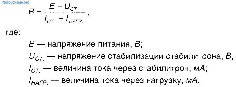
After rechecking the correctness of the installation, the analog of the strained zener diode is connected to the strum for 1 - 2 A and the resistor R6 sets the voltage for the discharged acid battery, say 11 V. Art.Stabilizers (Zener diodes, Z-diodes) are used for voltage stabilization, operation modes of various nodes of radioelectronic equipment. The principle of operation of the zener diode of foundations on the zener breakdown. n-r transition. This kind of electrical breakdown is observed at the inverted replacement of conductor transitions with increased voltage more than a critical sign. The cream of the Zener breakdown is known and victorious for stabilizing the voltage of avalanche breakdowns. Typical deposits of the struma through the conductor attachment (stabilitron) according to the magnitude of the applied direct or reverse voltage (voltage-ampere characteristics, I–V characteristics) are shown in fig. 1.1.
There are three modes of operation such as "hot emitter", "hot base" and "hot collector". The input signal is fed between the base of the transistor and the emitter through a capacitor, and the output signal is taken between the collector and the emitter. This scheme gives the input impedance of the average value and it can achieve a high voltage increase. Tsya scheme may increase the voltage strength, may be the power gain coefficient and even the low input impedance. The input signal is given between the base and the earth, and the non-inverted signal is taken between the emitter and the earth.
This circuit gives one more powerful voltage, like a "slide" to the input signal. Diagram of the little one 15 subsumovuє characteristics of three basic changes pіdsilyuvacha. In this rank, the power supply from a hot collector gives one more hot power and a high input impedance, at that hour, like a power supply from a hot emitter that the foundation give a high value of the coefficient of strength of the voltage, but can also give an average and low value of the input impedance.
Straight VAC necks of various stabilitrons are practical (Fig. 1.1), and the vertebrae may have individual features for the skin type of stabilitrons. Qi parameters: stabilization voltage; minimum and maximum stabilization strum; kut badly CVC, which characterizes the value of the dynamic support of the stabilitron (yogo brightness);
On the little one 16 it is shown - in the basic form - like a pair of pidsiluvachiv base type Rice. 11 can be combined at once to create a "differential" signal or "double-tailed bet", which generates an output signal, which is proportional to the difference between two input signals.
As in the guidance of the scheme, the input voltage is only applied to the input of one transistor, it changes output voltage of the second transistor and increase the voltage of the other transistor by a similar value, thereby giving a great differential voltage between the two collectors. On the other hand, as identical signals are fed to the inputs of both transistors, both collectors will collapse with the same numbers, and, in this way, the circuit will generate a zero differential output signal.
maximum tension of the rose; temperature coefficient of stabilization voltage (TKN) vikoristovuyut for rozrahunkіv schemes.
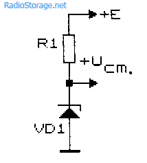
A typical zener diode switching circuit is shown in fig. 1.2. The value of the support to extinguish, R1 (for whom) is calculated according to the formula:
Scheme and design description
In this manner, the circuit creates an output signal that is proportional to the difference between the two input signals. In fact, the multivibrator is a two-cylinder. digital circuit which can be switched from the output to the high output camp, or to the outside, for the help of a trigger signal, which can be removed from the outer dzherel, or through automatic or automatic synchronization mechanism initiation. Transistors can be used in several basic types of multivibrator tubes, as shown in Figures 18 to 21.
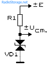
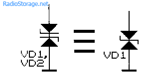
For voltage stabilization snake struma or a symmetrical exchange of iogo amplitude on the UCT equals vicorous symmetrical stabilitrons (Fig. 1.3), for example, type KS 175. Such stabilitrons can be vicorized to stabilize the voltage of a constant stream, including them without additional polarity. The "symmetrical" zener diode can be removed from two "asymmetric" ones, by including them symmetrically behind the circuit shown in fig. 1.4.
Scheme 18 is a simple binary multivibrator with a transverse connection with a manual drive, in the basic location of the skin transistor it resembles another collector, so that one transistor is automatically turned on, if the other one is switched on, and in the same way.
The little one 19 shows - the basic form - a monostable multivibrator or a single-cycle pulse generator circuit. In principle, this scheme is like a pair of cross-pairs of monostable lances, yak automatically sequentially launch one of one.
Vypuskayutsya promislovo napіvprovіdnikovі stabilіtroni allow stabilіzuvat naprugu vіd 3.3 to 180 V. low voltage: 3.3; 3.9; 4.7; 5,6 - ce KS133, KS139, KS147, KS156, etc. If necessary, take non-standard voltage stabilization, for example, 6.6, you can turn on two KS133 zener diodes in series. For three such stabilitrons, the stabilization voltage is set to 9.9 V. For a stabilization voltage of 8.0 V, it is possible to vicorize both stabilitrons KS133 and KS147 (tobto 3.3 + 4.7 V) or stabilitron KS175 and direct silicon tobto 7.5+0.5).
Function: stabilitron
Even though the two periods are not identical, the circuit generates an asymmetric output signal. Zreshtoyu, in fig. 21 shows the basic circuit of a Schmitt trigger or a sine-square signal switching circuit. Meta tsієї laborаї ї ї dіyalnostі - vyvchiti vykoristannya Zener diodes for pobudovi circuits, yak zabepechuє postіynu or regulovanuu vhidnu napruga in the range of input voltages and strumіv navantazhennya.
The voltage regulator is a circuit that is victorious for maintaining a constant output voltage during stress, so as not to lie in the wind during stress change. For example, "advancement" can be a system based on a microcontroller, as required constant voltage eating, navit as a stream will drink to lie in the activity of the system.

In situations where it is necessary to take a stable voltage of less than 2...3, vikoristovuyut stabistori - navіvprovіdnikovі diodes, which work on the straight line of the VAC (Fig. 1.1).
Significantly, instead of stabilisers, it is possible to successfully vicorize the primary germanium (Ge), silicon (Si), selenium (Se), arsenide-galvane (GaAs) and other types of conductive diodes (Fig. 1.5). Stabilization voltage in fallow, depending on the size of the stream, which flows through the diode, we become: for german diodes - 0.15 ... 0.3 b; for silicon - 0.5 ... 0.7 Art.
Figure 1 Zener diode regulator. Let us know about the opir, to which you installed the potentiometer. Obov'yazkovo adjust the range of the horizontal voltage and use it to increase the breakdown voltage of 1 volt. Discuss your results, explaining how a stabilitron is similar and winds up like a stellar diode.
Also, the scheme is also ineffective for smaller strums of pressure by extension to the maximum in that an excess strum flows in the zener, if there is no flow in the reservoir. Increasing the viprominuvacha-emitter or the booster of the Darlington streak strum can significantly improve the efficiency of the circuit of the regulator, as shown in the small picture. Figure 2, Adding an in-line pilot.
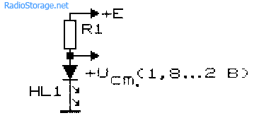
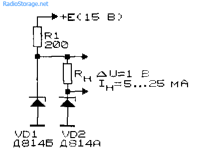
We especially focus on stosuvannya with the method of stabilizing the voltage of light-emitting diodes (Fig. 1.6) [Р 11/83-40].
Light-emitting diodes can simultaneously overcome two functions: for their lights, they can indicate the magnitude of the voltage and stabilize its value at a level of 1.5 ... 2.2 V. The stabilization voltage of the light-emitting diodes UCT can be determined by the approximate formula: L6/L2. (C), de X - the duration of the fluctuation of the light iodine in nm [Рl 4/98-32].
The battery voltage docks will not drop below 7 volts, if it will be close to 7 volts, throw it through the “stack” with ten diodes. Yakshcho need great voltage regulated, we can either win more diodes sequentially, or try another step. We know what straight voltage diode є to finish with a constant value in a wide range of minds, but also with a reverse voltage breakdown, and the voltage of the breakdown should sound more richly, lower straight voltage.
We changed the polarity of the diode in our circuit with one diode regulator and increased the voltage of life to the point where the diode “broke”, the diode was similarly regulated by the voltage at this point of breakdown, not allowing it to increase further on the little one.

To stabilize the voltage, it is possible to use a vicoristan coil of the I–V characteristics of electrical conductors (diodes and transistors) especially for these purposes, not recognized (Fig. 1.7, 1.8, and also Fig. 20.7). Tsya voltage (avalanche breakdown voltage) sound overwhelm 7 bytes and do not have high repeatability to type for heaters of the same type. For the sake of uniqueness of the thermal shock of the conductor fittings in such an unusual regime of their operation, the jet through them is not guilty of overshooting the frequency of a milliampere. So, for diodes D219, D220, the breakdown voltage (stabilization voltage) can be changed between 120 and 180 [R 9/74-62; R 10/76-46; R 12/89-65].
Symbol for zener diode. It’s a pity, if the diodes are normal, which straighten up, “lame”, the stench will ring out shyly. You can suggest a special type of diode, which can make the breakdown without failure. This type of diode is called a zener diode, as a symbol looks like a baby.
With a direct biased stabilitron, it behaves the same way, like standard vipryamnі diodes: the stench may directly drop the voltage, as if following the “diode equal” and become close to 7 volts. In the reverse displacement mode, the stench should not be carried out until quiet, until the voltage is applied is not within reach or the so-called voltage of the zener is not reached, and at that moment the building diode conducts a significant stream, and at this point the voltage drops on the new point of the zener diode. As long as there is tension, scho rises up return strum, which does not overwhelm the heat between the diode, the diode will not be damaged.
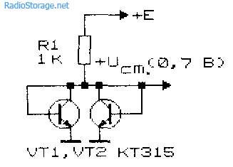
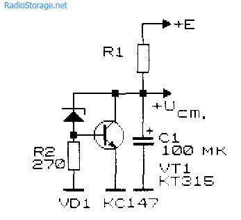
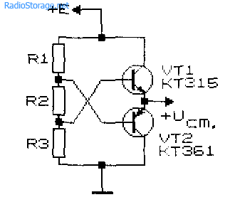
To stabilize a small voltage, the vicorist schemes presented in fig. 1.9 - 1.12. In the circuit (Fig. 1.9) [Goroshkov B.I.] there is a "diode" parallel connection of two silicon transistors. The stabilization voltage of the circuit is about 0.65...0.7 for silicon transistors and close to 0.3 for german ones. The internal opir of such an analogue of a stabitor is selected from 5 ... 10 ohms with a stabilization coefficient of up to 1000 ... 5000. However, with a change in temperature dovkilla the instability of the output voltage of the circuit becomes close to 2 mV per skin degree.
Zener diodes are manufactured with a zener voltage in the range from dekilkoh volts to hundreds of volts. The voltage of the zener diode changes insignificantly with the temperature i, as the value of the burnt resistor of the composite warehouse, can become from 5 to 10 vіdsotkіv according to the characteristics of the picker. However, stability and accuracy sound good for vikoristannya stabilitron as an attachment of a voltage regulator in the main scheme of living on a little one.
Be kind, give respect to the orientation of the stabilitron in the guidance of a larger scheme: the diode can be reversed and directed. We orientated the diode to the “normal” way, so that we could straighten it ahead, changing it by less than 7 volts, like a great diode that is rectified. If you want to conquer the power of the reverse breakdown of the diode, we can practice the regime of the reverse adoption. While the voltage of life is more than the voltage of the zener diode, the voltage that falls on the zener diode will be lost by about 6 volts.

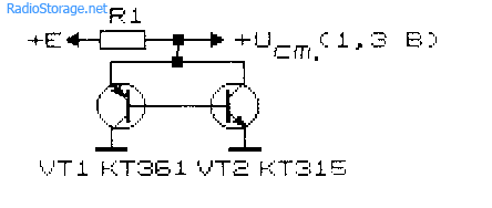
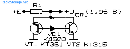
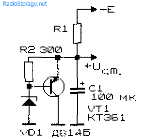
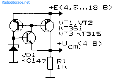
In the scheme of Fig. 1.10 [R 6/69-60; ВРЯ 84-9] after switching on the german and silicon transistors. Strum voltage of the zener diode analogue can be 0.02...10 mA. Attachments are shown in fig. 1.11 and 1.12 [Рl 1/94-33] structures r-p-rі p-r-p і v_d_znyayutsya tim, scho for the pіdvіschennya vyhіdnoї vprugi in one of the circuits between the bases of the transistor inclusions of silicon diode (one or a spigot). Strum stabilization analogues of stabilitrons (Fig. 1.11, 1.12) can be in the range of 0.1 ... 100 mA, the differential support on the operating distance of the VAC does not exceed 15 ohms.
Like and be-like napіvprovіdnikovy pristіy, stabilіtron sensitive to temperature. Above the world temperature is a suspense stabilitron, and the sparks seem to reduce the voltage, so it is possible to conduct a strum, it vibrates in the air, warmly, according to the Joule law. Therefore, it is necessary to be careful in order to design the regulator circuit in such a way that it does not overestimate the nominal intensity of the diode's rosette. It means that if the stabilitrons recognize failures through the supernatural exhaustion, it rises, the stench does not flicker, but scream.
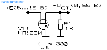
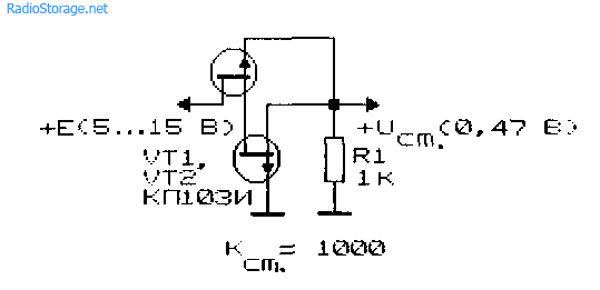
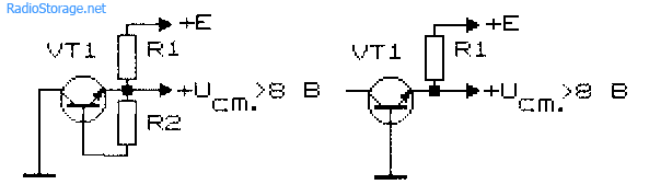
It is possible to stabilize a small voltage even for help field transistors(Fig. 1.13, 1.14). The stabilization coefficient of such circuits is already high: for a single-transistor circuit (Fig. 1.13) it reaches 300 with a voltage of 5 ... 15, for a two-transistor one (Fig. 1.14) in the same minds it exceeds 1000 [Р 10/95-55]. Internal opir tsikh analogues of stabilitrons to establish, vіdpovіdno, 30 ohm and 5 ohm.
It was not far off to reveal the diode in such a manner, the faults are easily revealed: the faults may fall to a zero voltage when it is placed straight ahead, like a piece of dart. Let's take a look at the mathematical scheme of a zener diode diode, which determines all the voltages, streams and pressures.
The tension is developed by the way of multiplying the struma by the voltage, so we can easily develop the expansion of the tension, like a resistor, or a zener diode. There would be enough stabilitron with a power of 5 watts, and a resistor of 5 or 2 W dissipation.
Like the transcendental expansion of tightness shkіdliva, why not design a scheme for the least amount of expansion? Why not just install a resistor on the arch of the high value support, by the same time separating the strum and saving the indicators of the pressure rise even lower? Take this circuit, for example, from a 100 kΩ resistor instead of a 1 kΩ resistor. To show respect, that the voltage of life, so the voltage of the stabilitron of the diode on the little one is identical to the rest of the butt.
The voltage stabilizer can be taken as a substitute as a zener diode analog of a dinistor (Fig. 1.15, see also section 2) [Goroshkov B.I.].

For stabilization of voltage at great strums folded schemes presented in fig. 1.16 - 1.18 [R 9/89-88, R 12/89-65]. To increase the struma, it is necessary to vicorate sweat transistors, installed on the heating.
Voltage stabilizer, which works in a wide range of life voltage changes (vіd 4.5 to 18 6) 1.19 [Goroshkov B.I.].
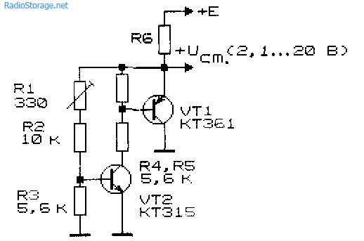
Looked at earlier, see stabilitrons and their analogues do not allow smoothly adjusting the stabilization voltage. To complete this task, control schemes of parallel stabilizers, similar to stabilizer diodes, are drawn up (Fig. 1.20, 1.21).
An analogue of a zener diode (Fig. 1.20) allows you to smoothly change the output voltage in the range of 2.1 to 20 [Р 9/86-32]. The dynamic support of such a "stabilitron" with a voltage surge of up to 5 mA becomes 20 ... 50 Ohm. Temperature stability is low (-3x10"3 1/°C).
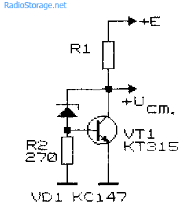
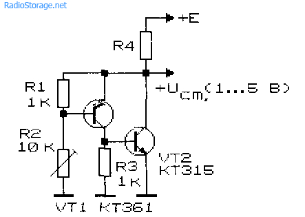
The low-voltage analogue of the zener diode (Fig. 1.21) allows you to set whether or not there is a voltage in the range of 1.3 to 5 V. The stabilization voltage depends on the ratio of resistors R1 and R2. The output of such a parallel stabilizer at a pressure of 3.8 is close to 1 ohm. The output stream is determined by the parameters of the output transistor and KT315 can reach 50 ... 100 mA.
The original diagrams of the selection of a stable output voltage are shown in fig. 1.22 and 1.23. Attachment (Fig. 1.22) is an analogue of a symmetrical zener diode [E 9/91]. For a low-voltage stabilizer (Fig. 1.23), the voltage stabilization coefficient is 10, the output stream does not exceed 5 mA, and the output opir changes in the range of 1 to 20 Ohm.

An analogue of a low-voltage zener diode of a differential type in fig. 1.24 may improve stability [R 6/69-60]. It is not enough to lie a little depending on the temperature and it depends on the difference in the stabilization voltage of two zener diodes. The increase in temperature stability is explained by the fact that for temperature changes, the voltage on both zener diodes changes at the same time and in close proportion.
Literature: Shustov M.A. Practical Circuitry (Book 1), 2003 rіk


