Self-loading charger attachment with a stable strum. Charging attachment with strum stabilization
Spent on the Internet a diagram of a two-channel charger attachment. I didn’t start working on two channels, for that which didn’t need it, I chose one. The scheme is fully working and miraculously charging.
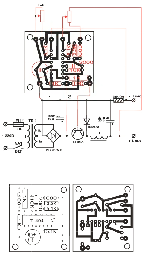
Scheme of memory for car batteries
Charger features
- Mere tension 220 Art.
- Output voltage 2 x 16 st.
- Strum charge 1 - 10 A.
- Strum discharge 0.1 - 1 A.
- The form of the struma charge is one-p_vper_odny vipryamlyach.
- Battery capacity 10 - 100 A/year.
- Battery voltage 3.6 - 12 V.
Description of the work: all charging and discharging attachments for two channels with separate regulation of the charge stream and discharge stream, which is more convenient and allows you to pick up optimal modes Renovation of the battery plates out of the current technical state. Change of the cyclic mode of renewal to a significant decrease in the output of gases in the air and acid through the outside of the change in the chemical reaction;
The strum discharge when charged with an asymmetric strum is responsible for becoming no more than 1/5 of the strum charge. In the instructions of the manufacturing plant, before charging the battery, it is necessary to perform a discharge in order to form the plates before charging. Shukati vіdpovіdne razryadne navantazhennya there is no need, enough vikonati vіdpovіdne perekannja at the outhouse. The control discharge of the bagzhano is carried out with a strum 0.05C in the capacity of the battery for 20 years. The scheme allows to carry out the molding of the plates of two batteries at the same time with a separate installation of a discharge and charging jet.
Strum regulators represent the key regulators of hard field transistors VT1, VT2.
At the Lanciugs zvorotny zv'azku optocouplers are installed, which are necessary for the protection of transistors in the form of navigation. When great Strum charge vpliv kondensatorіv C3, C4 mіnіmalny i mayzhe odnopoluperіodny Strum trivalіstyu 5 ms of the pause is 5 ms priskoryuє vіdnovlennya plates akumulyatorіv for rakhunok pause in tsiklі vіdnovlennya not vinikaє peregrіvu plates i elektrolіzu, pokraschuєtsya rekombіnatsіya іonіv elektrolіtu reaktsії atomіv Water that CHIN .
Capacitors C2, C3, working in the multiplier voltage mode, when the diodes VD1, VD2 are switched, create an additional impulse for melting large-crystalline sulfation and converting lead oxide into amorphous lead. Regulators strumu both channels R2, R5 live in parametric stabilizers voltages on zener diodes VD3, VD4. Resistors R7, R8 at the gates of the field-effect transistors VT1, VT2 interleave the gate stream to a safe value.
Transistors of optocouplers U1, U2 are used for shunting the gate voltage of field-effect transistors when rewired by charging and discharging streams. The control voltage is measured from the resistors R13, R14 at the drain, through the auxiliary resistors R11, R12 and through the intermediate resistors R9, R10 on the light diode of the optocoupler. When the voltage is increased on the resistors R13, R14, the transistors of the optocouplers turn off and reduce the control voltage on the gates of the field transistors, the streams in the lances drain-coil decrease.
Discuss the article JUST REGULATE THE CAR CHARGER
Not long ago I had a vinyl call charger attachment for car battery from the charging strum to the order of 3-4 amperes. For all sorts of wisdom, the hour, that bazhannya, was not particularly bulging. To that from the zasіkіv the splinter was old, but the circuit of the stabilizer of the charging jet was overwritten by the hour. Diskusіyu about greed - Skoda charge the battery with a stable strum is too much for the borders of the post. Let me just say that the scheme is simple, nadіyna, perevіrena hour. And more than that, nothing is needed.
Charging attachment scheme is available (for more - click on the picture):
The microcircuit (K553UD2) was installed a long time ago, but the shards were out in the presence of the bula, and spent an hour on experiments with the other, more modern, molting, won and the bula was installed. Yak resistor R3 buv vikoristany shunt like an old tester.
You can prepare yoga with nichrome, but it is necessary to remember that it can be sufficient. to pass through charging strum and do not spit at tsoma.
The shunt, inserted parallel to the ammeter, is selected, depending on the parameters of the apparent vibration head. The screws are installed directly on the head terminals.
The stabilizer board of the charger strum I will add an axis like this:

Yak transformer pіdіyde be-yaki vіd 85 watts and more. The secondary winding is 15 volts. Peretin drotu (diameter midi) vіd 1.8 mm.
Yak straight bridge 26MB120A. Vіn, zvichayno, poognuvaty for tsієї konstruktsії, but then again manually yogo montuvati - screwed on the radiator, piled up the clamps and that's it. Yogo is calmly replaced by some day place. Golovne, schob trimav necessary strum (about the radiator is also not forgotten).

For the body, a box was wrapped around the old radio. At the upper plane of the yogo, a row of openings was drilled for short ventilation.
The front panel is made from arched textolite. A shunt is installed on the ammeter, which needs to be regulated, spiraling on the indication of the test ammeter.

The transistor on the radiator is attached to the back wall of the case.

After folding, I will rebuild the struma stabilizer simply by shorting it between itself (+) and (-). The regulator is responsible for ensuring smoother regulation in the entire range of the charging jet. If necessary, select resistor R1.

Don't forget that when ALL the voltage drop falls on the control transistor! Tse crying yoga is stronger heating! Shvydko checked the re-verification of the bridge!
Now you can vicorate the charger attachment. It will stably support the charging jet in the entire charging range. Shards of attachments can't automatic switch-on after the completion of charging, the voltage on the battery is equal to the reading of the voltmeter.
CAR BATTERY CHARGER
CHARGER WITH TIMER
The start-up of the charger is carried out by pushing the "start" button on the front panel, when the voltage is applied to the circuit, the relay K1 operates and ensures "self-adjustment".
After the completion of the charging of the relay K1, the circuit will be switched on again. The adjustment of the scheme is already similar to the adjustment of the front scheme and it is not described here - well, this is the variant of the front scheme.
As a switch to the SA1 robotic mode, it is possible to switch the double toggle switch with three fixing mills. Relay K1 type RP-21 or similar to a 24 V coil. change strum 5 A., 220 Art.
CHARGER WITH STRUM STABILIZER
І CHARGING VOLTAGE CONTROL
One more charging attachment was selected for the circuit of the key stabilizer of the stream with a voltage control unit on the battery to ensure its activation after the charging is completed. To control the key transistor, the TL494 microcircuit (KIA494, KA7500V, K1114UE4) is widely expanded.
Attachment ensures the regulation of the stream of charge in the range of 1-6 A. (10 A. max) and output voltage 2 - 20 V. sq. div.
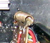
The most important element of the scheme is the L1 throttle. Vіd yakosі prepared to lay down the KKD scheme. Vimogi for yoga preparation is described in the previous diagram. As a core, it is possible to use a pulse transformer in the living block of TV sets ZUSST or similar.
It is even more important that the magnetic conductor should have a gap of approximately 0.5 ... 1.5 mm to avoid insufficiency at large streams. The number of turns to lie in a specific magnetic circuit and it is possible in the range of 15 - 100 turns of a PEV-2 2.0 mm wire. Since the number of coils is transcendental, then when the circuit is operating in the nominal voltage mode, there will be a remarkably quiet whistling sound. As a rule, the whistling sound is only heard at medium streams, and at high tension, the inductance of the choke for the magnetization of the core falls and the whistle is attached.
Yakschko whistle sound is prescribed with non-religious strips І with a deputy zb_lishenni stream Navantaged R_ZKO PRIKUK GRIETING VIKHIDNIY TRANSISTOR, meaning the core of the Magnіtoprovide Sladen for Roboti on Obranіy frequency of the MІKROSHI - Roboti Szb_lzyti Rack frequency of MіKrosshami pіdbor resistor R4 ABO Capacitor SZ ABO ABOUT ABOUT ABOUT BIVERS.
Due to the presence of the power transistor of the p-n-p structure in the circuit, it is possible to switch the power transistors structures n-p-p, as shown in the little one.

Like a VD5 diode in front of the L1 inductor, it is necessary to vicorate whether it is available diodes with a Schottky barrier, installed on the strum not less than 10 A. and a voltage of 50V, in the extreme low, it is possible to vicorate mid-frequency diodes KD213, KD2997 or otherwise. For a vipryamlyach, you can vikoristovuvat whether it’s a dim diode on a stream 10A or a diode mist, for example, KVRS3506, MP3508 or similar. Opir of the shunt in the scheme is necessary.
The range of regulation of the output stream is to lie down in the sp_v_dnoshnennia of the supports of the resistors of the lantsyug of the 15th microcircuit. At the bottom of the diagram of the position of the engine of the change resistor, the regulation of the struma voltage on the output microcircuit 15 can be increased from the voltage on the shunt when passing through the new maximum struma.
The change resistor R3 can be installed with either a nominal support, or it is necessary to add a constant resistor R2 to it to remove the necessary voltage on the output microcircuit 15. The change resistor to regulate the output voltage R9 can be large
By selection, the support of the resistor R10 is installed upper cordon output voltage. The lower boundary is dependent on the support of resistors R6 and R7, but it is not necessary to install less than 1V.
The microcircuit is installed on a small other board 45 x 40 mm., Other elements of the circuit are installed on the base and radiator. wiring diagram the connection of the other payment is directed to the little right-hander.
In the scheme of rewinding the power transformer TS180, but in the fallow, depending on the value of the required output voltage and the stream, the tension of the transformer can be changed. If there is sufficient output voltage of 15 V. and a stream of A., a power transformer with a voltage of 100 W is sufficient. Radiator area can also be changed up to 100 - 200 sq. div.
Priest can vikoristovuvatsya like laboratory block zhivlennya z regulation obezhennyam vyhіdnogo struma. With the correct elements, the scheme is repaired again and will require only further construction.
CHARGER ATTACHMENT
The biggest problems are the preparation of the accumulative inductor L1, the choice of the key transistor and the output diode. Parallel inclusion of a number of hard transistors does not solve the problem, so it is necessary to eliminate the voltage drop on the skin transistor, otherwise, the main focus of the stream is to take on one of the transistors and quickly overheat. Likewise, in the capacity of the key transistor, there should be a stronger N-channel power transistor, for example, IRFP264, there will be an additional auxiliary device, which will ensure the voltage shift at the gate by 15 V. At the external coil, connected to the accumulative choke.
The nomenclature of P - channel power field transistors, as it is easier to pass through the circuit, it is small and allows you to know the best option. You can beat the power npp transistors BUX20, specially designed for such attachments and safe stream switching up to 50 A. The best way to simply increase the output of the previously reviewed circuits is to stop the double-acting key regulation, supplementing the circuit with one more accumulative inductor, a key transistor and a diode. A scheme has been proposed to ensure such opportunities. Wimogi preparing accumulative throttles similar.
Transistors VI, VT2, output diodes VD3, VD4 and diode space VD1 are installed through mica gaskets on the heat radiator, as it is possible to vikorate the metal bottom of the attachment. The adjustment of the scheme is not in any way as described earlier and is not induced.
Through the rise of expansion tensions like storage capacitors CI, C5, only the capacitors of large expansions and with a shifted operating voltage can be broken.
For materials site http://kravitnik. people. en
Traplyatsya, if it is necessary to pass a stable stream through the light, close the charging stream of the battery, or try the life, and there is no rheostat under the hand. In this case, and not only, they will help to add special circuitry solutions, which surround, regulate and stabilize the strum. Gave a report on the schemes of stabilizers and regulators of the stream
Dzherela strumu, on the vіdmіnu dzherel naprugi, stabilize the vihіdny strum, changing output voltage so, schob strum through the vanishing of the zavzhdya, having lost the same.
In this order, the jerelo struma is wafted in the dzherel of the tension, like water is wafted in the land. Typical zastosuvannya dzherel strumu - zhivlennya svetlodiodіv, zadzhannya akumulyatorіv lean.
Respect! Do not confuse the struma stabilizer with the voltage stabilizer! Tse mozhe nasty skint =)
Simple strumu stabilizer on KRENKA
For this stabilizer, it is enough to strum KR142EN12 or LM317. Tse regulation stabilizers building voltages with streamers up to 1.5A, input voltages up to 40V and increase intensities up to 10W (under pretrial thermal conditions).
Scheme and zastosuvannya shown in the figures below

The damping of these microcircuits is not great - close to 8 mA and the damping practically does not change when changing the struma that flows through the roll or changing the input voltage. Like Bachimo, in the case of better schemes, the LM317 stabilizer works like a voltage stabilizer, increasing on resistor R3 constant voltage, Yake can be regulated in the current range with a bud_velny resistor R2 In this case, R3 is called a current-setting resistor. Oskіlki opіr R3 nezminny, then the strum through the new one will be stable. Strum at the entrance roll will be approximately 8mA more.
In this rank, we took away a simple strum stabilizer, which can be stagnant like electronic advancement, dzherelo struma for charging batteries, etc.
Integral stabilizers should react quickly to changes in input voltage. The shortcoming of such a regulator is the great support of the current-setting resistor R3, and as a result, it is necessary to install more tightening and expensive resistors.
A simple strum stabilizer on two transistors
To achieve a wide width, a simple stabilizing strum on two transistors was used. The main disadvantage of this scheme is that the stability of the struma in navantage is not very good when the voltage is changed. Vtіm, for bagatioh zastosuvan fit such characteristics.
Dali shows the scheme of the stromu stabilizer on transistors. This circuit has a current-setting resistor є R2. When the stream is increased through VT2, the voltage on the current-setting resistor R2 is increased, as at a value of approximately 0.5 ... 0.6V, the transistor VT1 starts to turn off. Transistor VT1 starts to close the transistor VT2 and the stream changes through VT2.


Deputy bipolar transistor VT2 can be zastosuvat - pole transistor.
Zener diode VD1 is selected for voltage 8 ... 15V and is necessary for vibrations, if the voltage is high, and the shutter can be broken field effect transistor. For tight MOSFETs, the voltage should be close to 20V. The following shows a circuit of a strum stabilizer with MOSFET victories.

It is necessary to check that MOSFETs are energized when the voltage on the gate is not less than 2V, and the voltage will increase, which is necessary for the normal operation of the strum stabilizer circuit. When charging the batteries and other tasks, it will be enough to turn on the transistor VT1 with the resistor R1 without interruption to the core of life as shown in the little one:

Strumu stabilizer circuits on transistors require the value of the strum resistor for a given value of the struma to be approximately twice less, lower for circuits with a stabilizer on KR142EN12 or LM317. Tse allows you to set the current-setting resistor of less tension.
Stabilizer strum on the operating room (on the OP)
It is also necessary to select the regulation at wide boundaries of the strum stabilizer or the strum stabilizer with a current-setting resistor by an order of magnitude, or put two lower, lower on the diagrams shown earlier, you can zastosuvat circuit with a pіdsiluvachem pardon on the op-amp (operational pіdsiluvachi). The scheme of such a strumu stabilizer is shown in fig.

This circuit has a current-setting resistor R7. Op-amp DA2.2 strengthens the voltage of the current-setting resistor R7 - the strength of the pardon is increased. Op-amp DA2.1 porіvnyuє prіvnyuє prіvnjuє prіvnjuє prіvnjuє prіvnjuє prіvnuє prіvrugu prіvrugu pomiluє і reguliuє stan field effect transistor VT1.
Please be aware that the circuit will require a lot of life to apply to the XP2 socket. The voltage of life is due to the circuit, which is sufficient for the robotic components, and not to overshoot the value of the voltage due to the breakdown of the MOSFET VT1 gate.
Like a reference voltage generator in the circuit in fig. 7 the microcircuit DA1 REF198 with an output voltage of 4.096V was installed. If the microcircuit is expensive, then you can replace it with a variable roll, and if the voltage of the circuit (+ U) is stable, then you can do without a voltage stabilizer in this circuit. In this case, the changeable resistor R does not come to REF, but to + U. At the time of the electronic circuit, the 3 DA2.1 wiring diagram can be connected directly to the output of the DAC.
To adjust the circuit, it is necessary to set the link of the change resistor R1 at the top behind the position circuit, set the necessary value of the struma with the auxiliary resistor R3 - it will be maximum. Now the resistor R1 can be used to regulate the strum through VT1 to 0 up to the maximum strum set when adjusted. Elements R2, C2, R4 are necessary for zabіgannya zbudzhennya circuit. Through the qi elements of the timchas, the characteristics are not ideal, as can be seen from the oscillogram.

On the oscillogram, promin 1 (zhovty) shows the voltage of the navantazhuvanny IP (dzherela life), promin 2 (black) shows the voltage on the current-setting resistor R7. As you can see, by pulling 80 microseconds through the circuit, the flow of the strum at the spear has more time for insertions.
Strumu stabilizer on the microcircuit of the impulse voltage stabilizer
In addition to the stabilization of the struma, it is necessary not only to practice in a wide range of voltages and tension, to revive, but also high KKD. In such situations, compensatory stabilizers are not suitable and change them to come impulse stabilizers (keys). In addition, impulse stabilizers can, with a small input voltage, take high voltage on the adventure.
- Live voltage 2...16.5V
- Vlasne 110uA
- Exhaust pressure up to 15W
- KKD at jet voltage 10mA…1A reach 90%
- Reference voltage 1.5V
For a small indication, one of the options for including a microcircuit, we take it as the basis of our circuit.

The stabilization process is simplified as follows. Resistors R1 І R2 є Dilnikimi VihIno-ї ї мильны мікрохнахми, как тільки поілель протогона и и ло по двинок мікрохрахми михосна михоска кмерше замужена (1,5V) Мікорохма смышує Вохідну на на ина на ина месское на на міпросхем сбільшуєє input voltage.
Obviously, in order to change the control lances in such a way that MAX771 reacted (and regulated) the external strum, we should also stabilize the strum.
Below is shown a modified circuit with an exchange of output voltage and a variant of the transition.
With a small voltage, while the voltage drop on the strumming resistor R3 is less than 1.5V, the circuit in Fig. 10a works as a voltage stabilizer, stabilizing the voltage on the equalization of the stabilitron VD2 + 1.5V. As the strum of ambition becomes great, the voltage drops on R3 and the circuit switches to the strum stabilization mode.
Resistor R8 is installed in that direction, so that the stabilization voltage can be larger - more than 16.5V. Resistor R3 is current-setting and is protected by the formula: R3 \u003d 1.5 / Ist.
A short circuit is to achieve a large voltage drop on the streaming resistor R3. This small amount is used for the installation of an operational switch to strengthen the signal from the resistor R3. For example, if the resistor needs to be changed by a factor of 10 for a given stream, then the power supply at the op-amp is responsible for increasing the voltage, which falls on R3 for 10 times.
Visnovok
Later, a piece of schemes was looked at, which would serve as a function of stabilizing the struma. Obviously, qi schemes can be improved, zbіlshyuuchi shvidkodіyu, the accuracy is too thin. You can zastosovuvaty as a sensor strumu spetsializovanі microcircuits and the work of supra-pressure regulating elements, and the circuits are ideally suited for quiet situations, if you need to create a tool to make your work easier or to turn a singing stake into a factory.
In this article, let's talk about one more charger for a car. Charge the batteries with a stable jet. The charger circuit is shown in small 1.
As a fencing transformer in the rewinding circuit, the transformer is for the TS-180 lamp TV, and TS-180-2 and TS-180-2V. For rewinding the transformer, it is carefully disassembled on the back of the head, not forgetting to mark the gluing core with what sides, it is not possible to confuse the position of the U-like parts of the core. We will wind the secondary windings. The screen winding, as if you were charging with a charger only at home, you can get rid of it. If I am transferring vikoristannya I will attach it to other minds, then the screen winding will be lifted. The upper insulation of the primary winding is also taken into account. After that, the cats will seep out with bakelitis varnish. Naturally seeping on the virobnits vіdbuvaєtsya at the vacuum chamber, as there are no such possibilities, then leaking in a hot way - hot varnish, rosemary in a water bath, throwing cats and checking for a year, until the stink does not leak varnish. Then let's give the stained varnish and put the coils in a gas oven with a temperature of about 100 ... 120? In extreme cases, the winding of the coils can be soaked with paraffin. After that, it is worth noting the insulation of the primary winding with the paper itself, and also with see-through varnish. Dali motaєmo on kotushki for ... at once, it’s hard. To change the idling struma, and the veins are clearly growing, so we don’t have the necessary ferropaste for gluing twisted, separate cores, we will vikoristovuvat all turns of the windings of the coils. I so. The number of turns of the primary winding (div. table) is good 375 +58 +375 +58 = 866 turns. The number of turns per volt is more than 866 turns per volt, or 3.936 ≈ 4 turns per volt.
Calculate the number of turns secondary winding. Asking the voltage of the secondary winding 14 volts, which will give us a voltage of 14 √ 2 = 19.74 ≈ 20 volts at the output of the rectifier with filter capacitors. Vzagali, chim less voltage, tim lesser stress at the sight of heat can be seen on the transistors of the circuit. And so, 14 volts multiplied by 4 turns per volt, we take 56 turns of the secondary winding. Now let's put the strum of the secondary winding. Sometimes it is necessary to charge the battery quickly, which means it is necessary to increase the charging strum for one hour to the boundary. Knowing the overall pressure of the transformer - 180W and the voltage of the secondary winding, we know the maximum stream 180/14 ≈ 12.86A. The maximum strum collector of the KT819 transistor is 15A. The maximum intensity according to the voltage of the transistor in the metal housing is 100W. So, with a stream of 12A and an intensity of 100W, the voltage drop on the transistors cannot be overestimated ... 100/12 ≈ 8.3 volts and it’s worth remembering that the temperature of the transistor’s crystal does not exceed 25? It means that a fan is needed, and a transistor is practical between its capabilities. We choose a strum equal to 12A for the mind, that at the skin shoulder we immediately cost two diodes of 10A each. For the formula:
0.7 multiplied by 3.46, is it possible to take the diameter of the dart? 2.4 mm.
You can change the strum to 10A and plug the wire with a diameter of 2mm. To ease the thermal regime of the transformer, the secondary winding can not be covered with insulation, but simply coated with a ball of bakelite varnish.
Diodes KD213 are installed on the plate radiators 100x100x3mm made of aluminum. You can install it directly on the metal body of the charger through the mica gaskets with the thermal paste. The replacement of the 213th can be loaded with D214A, D215A, D242A, but it’s better to use the diodes KD2997 with any letter, the typical value of the direct voltage drop for them is 0.85V, then, with a stream of heat charge of 12A, they can be seen 0,8 1 10W. Maximum straightening constant strum tsikh diodіv dorіvnyuє 30A, that and koshtuyut stink is not expensive. The LM358N microcircuit can work with a voltage input signal close to zero, I have not learned any analogs. Transistors VT1 and VT2 can be blocked with whatever letters. Like a shunt zastosovana zastozovanka zі ludzhenoї zhestі. Rosemary of my wife virizanoi from a tin can () - 180 × 10x0.2 mm. With resistor values R1,2,5 assigned on the circuit, the strum is regulated approximately from 3 to 8A. Chim smaller nominal resistor R2, tim more strum I will add stabilization. Read how to develop an additional opir for a voltmeter.
About the ammeter. I have a husband of virizan for more indicated rosemaries, as a whole vipadkovo may opir 0.0125 ohm. Mean when passing through the struma at 10A, at its inlet U=I R = 10 0.0125=0.125V = 125mlV. In my case, a vibrating head was installed, which was opir 1200 Ohm at a temperature of 25C.
Lyric entry. A lot of radioamators, grounded shunts for their ammeters, so I don’t pay any attention to the temperature fallacy of all the circuit elements that are chosen by them. You can talk about this topic to the point of indistinctness, I will give you just a small butt. Axis active opir frames of my vimiryuvalnoy head for different temperatures. І for what kind of minds should a shunt be opened?
Tse means that the strum, setting in the minds of the home, will not match the strum, set by the ammeter in a cold garage collection. If you don’t care about it, then just change the switch to 5.5A and 10 ... 12A and everyday fittings. Don’t fight, so that you don’t break them, I’ll add one more great plus of the charger to stabilize the charge stream.
And so far. When supporting the frame, which is equal to 1200 Ohm and the struma of total respiration of the arrow, I will attach 100 μA, we need to apply a voltage to the head 1200 0.0001 = 0.12V = 120 mlV, which is less, lower voltage drop on the shunt support at 10A. To this end, put an additional resistor, more often a substroyuval one, so that you don’t suffer from the pickup.
Installation of the stabilizer vikonano on another board (div. photo 3). I surrounded the maximum charge for myself with six amperes, so with a stream of stabilization of 6A and a drop in voltage on sweaty transistors 5B, you can see the exhaustion at this temperature of 30W, and blowing a fan on the computer, this radiator heats up to a temperature of 60 degrees. With a fan, it’s too rich, a necessary efficient radiator. Approximately estimate the need. My pleasure to you - put the radiators insured for robotic PP fittings without a cooler, let better rozmiri fit it more, but with the spikes of the cooler, nothing will burn.

When analyzing the output voltage of the oscillogram, the oscillogram was noisy, which indicates the instability of the robot circuit tobto. the scheme was buzzing. I had a chance to supplement the circuit with a capacitor C5, which ensured the stability of the robot and the building. So, in order to change the voltage on KT819, I changed the voltage at the output of the rectifier to 18V (18 / 1.41 \u003d 12.8V, so the voltage of the secondary winding of my transformer is 12.8V). Take advantage of the little ones with a hand-me-down pay. Good bye. K.V.Yu.
Addition. Analog LM358 - KR1040UD1


