The formula for the rozrahunka of a three-phase struma short zamikannya. Vector diagrams of streaks and stresses with a short-circuited short circuit in a measure
ROZAHUNCHNA ROBOT
Topic:"ROZRAHUNOK OF THE TWO-PHASE SHORT ZAMIKANNYA"
Meta robots: Rozvitok navychok іz rozrahunku short zamikan in electric lances.
Option number 2.
Zavdannya No. 1. Tiny 1 shows a two-phase short circuit. Designate:
1. Revisiting the direct sequence of two phases (2Zf);
2. Strum short chime (Ik);
3. Phase EPC (EA).
So how is the voltage at two-phase short flicker do not take revenge on warehouse zero sequence in any point of measure, may be satisfied with the mind:
3Uo = UAK + UBK + UCK = 0, with UA = EA
Rice. 1. Scheme of a two-phase short circuit
Exit data: ZB = 25 Ohm; ZС = 15 Ohm; EBC = 90; UVK = 100 St.
Hіd vyshennya:
Figure 1 shows a metal short circuit between phases INі W LEP. Under the direction of interphase EPC EBC(fig.1) IVCіISk.
Їх values are assigned to the following formula:
IBefore(2) =ЄВС /2 ZF, (1)
de 2 ZF- A new opir of the direct sequence of two phases.
The latest opir of direct sequence 2 ZF stands for the formula:
2 ZF= ZIN+ ZW, (2)
de ZIN, ZW- The latest opir of phases B and C is clear.
1. Behind formula (2) is the latest opir of the direct sequence of two phases (2Zf):
2 ZF= 25 ohm + 15 ohm = 40 ohm.
2. Behind formula (1) is the strum of a two-phase short circuit:
IBefore(2) \u003d 90 V / 40 Ohm \u003d 2.25 A.
Strums in advanced phases are equal to the values, but prolongations in phase, and strums in non-slow phases are equal to zero (in case of unbalanced pressure): IVC= ISk, IA = 0.
Strum of zero sequence (NP) with two-phase short circuit every day, so the sum of the strum of three phases I A+ I B+ I C= 0 .
Voltage of non-shocked phase BUT however, whether it is a point of measure and a good phase of the EPC: U A= E A. Oscilki interfacial voltage at metal short circuit at short circuit point U BCbefore= U Bbefore – U Cbefore= 0, then U Bbefore = U Cbefore,
i.e., the phase voltages of the different phases in the short circuit area are equal per module and vary in phase.
Oskіlki phase voltage in a two-phase short circuit does not avenge warehouse NPs, be it a point of measure, you can be satisfied with your mind:
Vrakhovuychi, what is the mist of KZ U BK= U CKі U AK= E A, known
![]() (3)
(3)
Also, in the case of a short circuit, the voltage of the skin ear phase is more than half the voltage of the non-shock gene phase and it is the same as the sign.
3. From formula (3) we can change the phase EPC of the non-shocked phase (EA):
EA=–UBK /2.
EA=– 100 V /2 = – 50 Art.
Two-phase short circuits are characterized by two features:
1) the vectors and strums and the voltages are asymmetrical, but the system is new, what can we say about the presence of warehouse NPs. The presence of non-symmetry shows that the streaks and tensions may have a warehouse sequence (OP) in order from a straight line;
2) the phase voltage in the short circuit area is greater than zero, only one phase voltage is reduced to zero, and the value of the other two is one 1.5 UF. Therefore, two-phase short circuit is less unsafe for the stability of EEC and saves electricity, lower three-phase.
Task #2.
Paint the circuit for connecting the voltage transformer to the star. Explain to the robot the meaning of the scheme. |
|
Vіdpovіdno to GOST 11677-75 cob and kіntsi primary and secondary windings of transformers are assigned to the designated order. Cobs of windings of single-phase transformers are designated by letters A, and ends - X, x. Great letters go up to the windings of the higher voltage, and small letters - to the windings of the lower voltage. As a transformer, the crim of the primary and secondary, and the third winding with the intermediate voltage, її the cob denotes Am, and the end Xm.
In three-phase transformers, the cob and the end of the windings mean: A, B, C; X, Y, Z - Vishcha voltage; Am, Bm, Cm; Хm, Ym, Zm – mean stress; a, b, c; x, y, z - lower voltage. In three-phase transformers, the phases are connected to the star of the cream, the cob of windings is connected to the neutral, so that the main point of the termination of the ends of all windings. Її mean O, Om and O. On the little 1, a b shows the scheme for connecting the windings to the star and the tri-coil so that they are depicted for three-phase transformers.
DIV_ADBLOCK258">
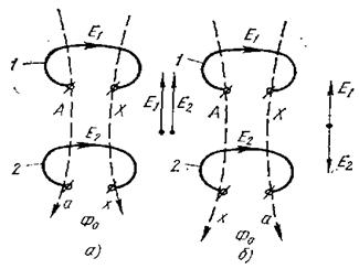
a - eds E1 and E2 move in phase; b - EDC E1 and E2 failures in phase by 180 °; 1 - a turn of the primary winding; 2 - coil secondary winding
Figure 2 - Kutove displacement of vectors electrical disruptive forces in fallow
It is permissible now that we have changed the designation of the cob and the end of the turn in the secondary winding (Figure 2, b). Any change in the physical process of guiding the EDC will not be seen, but if it is extended to the end of the turn, the EPC will change directly on the length, so that it will not be straightened from the cob to the cob, but on the other hand - from the cob (x) to the cob (a). Sparks in turn 1 did not change anything, we are to blame for the EDC and E2 shifting in phase by 180 °. In this way, it is simple to change the value of the endpoints of the equal to the apex displacement of the eds vector in the winding by 180 °.
However, the EDC can change directly even in that case, if the cob and the ends of the primary and secondary windings are reversed at the same time. On the right, in that the transformer windings can be turned right and left. The winding is called the right winding, as when winding, the turns are wound behind the annual arrow, so they are laid with the right screw line (Figure 3, upper winding). The winding is called left-handed, as when winding, the windings can be wound against the year's arrow, so they are laid along the left-handed screw line (Figure 3, lower winding).
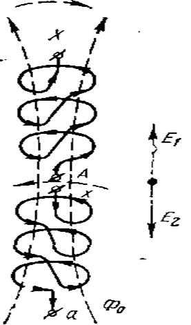
Figure 3 - Kutove offset of the EPC vectors fallow in the direction of the winding of the windings
As you can see from the little one, the insults of the windings may be the same as the signs of the ends. Because the windings are pierced by one and the same thread, the skin coil will have the same ODS directly. However, through the winding time, the total edc of all successively wound turns at the skin winding is different: in the first, the eds are straightened from the cob A to the end of X, and for the second - from the end of the x to the cob a. Also, with the same designation of the EDC of the primary and secondary windings, they can be offset by 180 °.
For a single-phase transformer, the vectors and eds of the windings can either be increased, or alternatively rectified (Figure 4, a, b). Since there is only one such transformer, then for the spozhivachiv it is absolutely baiduzhe, as if directing the EDC in the windings. Also, three single-phase transformers work at once on the line triphasic struma, then it is necessary to work correctly, so that the skin vector and EMF will be straightened either as a small 4, a, or as a small 4, b.
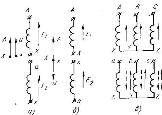
a, b - single-phase; in - three-phase
So it is self-contained and a skin three-phase transformer. Although in the primary windings of the EDC in all phases there may be the same direct, then in the secondary windings of the direct EDC, it can be similar (Figure 4, c). It is obvious that in the secondary windings the winding is directly wound, and the indications of the fault lines are also the same.
When the windings are pardoned, the windings are wound with less direct winding, or if the voltage is incorrectly connected, which is taken away by the spontaneous, it will change sharply, and the normal work will collapse. Particularly unfriendly minds are blamed at times, for example, in one measure, a sprat of transformers works at the same time, in which phases are destroyed between the linear ODS of different. In order to get rid of the damage to the robots, the next transformers with the main winding displacements of the vector windings.
Directions of the vectors of the EDC and the windings between them are usually characterized by groups of windings. In practice, the displacement of the EDC vectors of the PN and SN windings according to the reference to the EDC vectors of the HV windings is indicated by a number, which, being multiplied by 30 °, gives the cut of the vectors. This number is called the group of windings of the transformer.
So, when the vector eds of the windings is switched on in a straight line (the offset is 0 °), the group 0 will appear (Figure 4 a). Kutove offset 180 ° (Figure 4 b) for group 6 (30 x 6 = 180 °). As we have seen, in the windings of single-phase transformers there can be only such coils, so they can only have 0 and 6 groups of circuits. Winding windings of single-phase transformers for style indicate I / I - 0 and I / I - 6.
In three-phase transformers, the windings of which can be connected to a star or a tri-coil, it is possible to establish 12 different groups with a single phase of the vector line units from 0 to 360 through 30 °. Of the twelve possible groups of z'ednan in Russia, two standardized groups are standardized: 11-a and 0-a z with phases 330 and 0 °.
Let's look at it as an example of the Y / Y and Y / Δ schemes (Figure 5, a, b). Windings, stitched to one shear, picturing one under the other; the winding of all windings (primary and secondary) is accepted the same; Directions of the phase EDCs are shown by arrows.
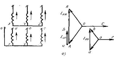
Figure 5 - Removing the group of circuits from the circuit zirka - zirka (a) We will let the vector diagram of the EDC of the primary winding (Figure 5, a) so that the EDC vector of the phase Z is horizontal. Z'dnavshi kіnts_ vekotorіv A і B, otrimaemo vector linear EDS EAB (AB). Let's have a vector diagram of the EDC of the secondary winding. Scatters of directing the EDC of the primary and secondary windings, however, the vectors of the phase EDC of the secondary winding will be in parallel with the respective vectors of the primary winding. The last points a і b і having attached the vector Eab (ab) to point A, we change the way that the windings between the linear ODS of the primary and secondary windings are equal to 0. Also, in the first butt, the winding group 0. / Yn -0, which reads “star with a neutral neutral”.
When looking at another butt (Figure 5 b), it’s safe to say that the vector diagram of the primary winding eds is induced the same way as in the front butt. When prompted by the vector diagrams of the EDC of the secondary winding, there are traces of memory, that when the phases and linear EDCs are connected to the tricot, both for the magnitude and for the direct one.
We will be the EDC vector of phase C, directing it parallel to the vector Z of the primary winding. The end of the phase z (point z) starts with the cob of the phase b, to that, in the end of the vector h, the vector eds of the phase a is conducted, to that, in the end of the vector b (point y), the vector eds of the phase a is drawn parallel to the vector A. , abc the vector ab is the whole line eds Еab. Having added the Eab vector to the point A, we switch over that the faults are due to the extension to the EAB vector at a cut of 30 ° at the bik viperedzhennya. Also, the Eab vector goes 330 ° (30 ° x 11 = 330 °) in the EDC vector of the HV winding. Otzhe, at this butt, the group of windings is 11. Tse is designated as follows: Y / Δ -11, which reads: “zirka - trikutnik - eleven”.
For a three-winding transformer, the group of windings is set in the same way; at which the windings are looked at in pairs: the first one is one of the other two. If the meaning of Yn / Y / Δ is 0 - 11, then you need to read it like this: “star with a neutral neutral - star - trikutnik - zero - 11”. Tse means that in the analyzed triwinding transformer, the HV winding is connected to the star with the zero point shown, the SN winding is to the star, the PN winding is to the three-coil, the group of HV and SN windings is zero, the VN and LV windings are 11.
We looked at only two groups of z'ednannya - 0 and 11. Changing the designation of the endings (by a circular movement of the designation), you can take other groups from 1 to 10. However, these groups did not know the width and are narrowed even more rarely. Russia has more than three standardized groups: Y/Y - 0, Y/Δ - 11 for three-phase transformers, I/I - 0 - for single-phase transformers.
List of references
1. that in. Electrical engineering /, : Navch. help for universities. - M.: Vishcha shkola, 2007. - 528 p., il.
2., Nemtsov: Navch. help for universities. - 4th species., Rev. - M.: Vishcha shkola, 2009. - 440 p., il.
3. Fundamentals of industrial electronics: A handyman for non-electrotechnical. specialist. university/, O M. Knyazkov, A E. Krasnopіlsky, ; for red. . - 3rd view., Rev. that dod. - M.: Vishch. school, 2006. - 336 p., il.
4. Electrical engineering and electronics in 3 books. For red. Book 1. Electrical magnetic lancers. - M.: Vishcha school. - 2006
5. Electrical engineering and electronics in 3 books. For red. Book 2. Electromagnetic attachments and electrical machines. - M.: Vishcha school. - 2007
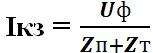
Strum three-phase short circuit in terms of living life, it is indicated in kiloamperes by the formula:
de U N PN - average nominal interphase voltage, taken as the basis; for a measure of 0.4 kV, a voltage of 400 is taken as the base voltage;
The latest total opir of the lansyug to the point of a three-phase short circuit, which is the basis of the direct sequence and follows the formula in miliomas:
de R 1∑ - total active opir lancer to the short circuit point, mOhm;
X 1∑ - total inductive support to the short circuit point, mOhm.
Total active opir includes opir of advancing elements:
Total inductive opir to retaliate opir of advancing elements:
Two-phase strum K3 calculated for kilometers for the following formula:
![]() ,
,
de - average nominal interphase voltage, taken as the basis, V;
i - more total support of the direct and pivotal sequences, moreover, one, mOhm.
Viraz (19) can be written as
![]() =,
=,
de - outside the opir lansyug up to the month K3 with a two-phase short-circuit, mOhm.
![]() ,
,
The strum of a single-phase short circuit is assigned to the formula:
Totally active and inductive support of zero sequence up to month K3, viable, mOhm.
36. Thermal stability of devices.
The thermal stability of electric devices is called the building of their vitrimuvat without delay, which the farther robots cross, the thermal injection of strums, which flow through the streak-guiding parts of a given trivality. A key characteristic of thermal stability is a stream of thermal stability, which flows through a long span of time. The most stressful is the short-circuit mode, in the process of such a stream in equal parts with nominal ones, it can increase dozens of times, and the tension of the heat source can grow hundreds of times.
37. Dynamic stability of devices
Electrodynamic resistance the device is called yoga building to resist electrodynamic sound(FOOD) Tsya value may vary or bezperedno amplitude values struma i day, if the mechanical stress in the details of the apparatus does not go beyond the permissible values, but the multiplicity of the jet should be of amplitude par strumu. Sometimes electrodynamic stability is evaluated. wild values strum for the period (T = 0.02 s, f = 50 Hz) after the cob short circuit.
38. The order of rozrahunku strum_v short zamikannya.
Short hums (SC) are called the strumming parts of the different phases, or potentials between themselves or with the hull of the possession, from the ground, between the electrical supply lines or in the electrical receivers. A short pause can be attributed to various reasons, for example, poor insulation support: in a watery, chemically active medium; with unacceptable heating and cooling insulation; mechanical damage to insulation. A short pause can be blamed on the occasion of pardons to the personnel during operation, maintenance and repairs.
With a short fading way, the struma “shortenes”, the shards of wine in the same place with a lansy hugging the opir navantage. Therefore, the strum rises to unacceptable values, as if the liveliness of the lancer does not join under the deed of the zakhist. The voltage may not turn on for obviousness, I will add a zakhista, as a short flicker at the distant point and, later, opir electric lansyug to show up too big, and the size of the struma z tsієї cause to show up insufficient for spratsovuvannya zakhist. A strum of this magnitude may be sufficient for an unsafe situation, for example, for igniting wires. A short-wave strum also copes with an electrodynamic surge on an electric device - conductors of this part can be deformed under a surge of mechanical forces, which is blamed for great strums.
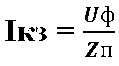
Vykhodyachi z vishcheopisannogo, pristroї zahistu sled podbirati for the minds of the magnitude of the struma of a short zamikannya (electrodynamic mіtsnіst, vzkazuetsya in ka) for the month of their installation. At zv'yazku z tsim when you select a zakhistu vinikaє it is necessary to rozrahunka strumu short zamikannya (TKZ) electric lansyug. Short-circuit strum for single-phase lanceug can be developed using the formula:
de Ikz - short circuit strum, Uf - phase voltage of the merezhі, Zp - opir of the lance (loop) phase-zero, Zt - last opir of the phase winding of the transformer on the low voltage side.
de Rp – active support of one short chirp drotu lanceug.
de ro - nursery opir conductor, L - dozhina of the conductor, S-area of the transverse section of the conductor.
Xp-inductive opir of one lancet short chirp (sound is taken from a 0.6 ohm / km rozrahunka).
Transformer short-circuit voltage (% VID Un):
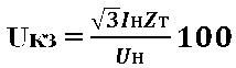
Zvіdsi povny opіr phase winding of the transformer (Ohm):
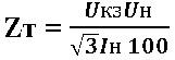
de Ukz - short circuit voltage of the transformer (% vіd Un) induced in dovіdniki; Un - Rated voltage transformer, Іnnom_nalny strum transformer - also taken from dovіdnikіv.
Navedі rozrahunki vykonuyutsya at the stage of design. In practice already working objects zrobiti tse important through the lack of weekends. Therefore, when rozrahunka strumu short zdebіkannya zdebіlshego it is possible to take the phase winding of the transformer Ztr equal to 0 (actual value ≈ 1∙10-2 ohm), then:
Suggested formulas are suitable for ideal minds. Unfortunately, the stench does not protect such a factor, as it is twisted too thinly, yakі zbіlshhuyut active warehouse lance Rp. To that I can give a more accurate picture of the more uninterrupted vimiryuvannya support of the "phase-zero" loop.
39. Strum of dispensing, setting of the strum, strum of the automatic vimikacha.
Rozchipluvach
The strum, which flows through the electromagnetic rozchіpuvach of the automatic vimikach, to cause the automatic machine to turn off when the swid and digit is moved over the nominal strum of the automatic vimikach, which sounds when there is a short flicker in the wire, which is protected. A short twitch is accompanied by an almost growing high strum, which electromagnetic blower, which allows you to practically mittevo vplyvat on the mechanism of opening the automatic vimikach with a swedish growth of the struma, which flows through the coil of the solenoid of the opening. The speed of the operation of the electro-magnetic opening does not exceed 0.05 seconds.
Set point struma on the scale is marked by the plant; at the table there is a creak, especially for the number of points, it is assigned to the number of heads of the nominal stream of the rozchiplyuvach. Between the lower and upper boundaries, assigned on the scale, the settings are adjusted smoothly.
Vіdsіkannya e the minimum value of the struma, which calls out the mittve of the automatic machine).
Appointment and mind motivate vector diagrams. For z'yasuvannya minds of robots and relays manually vikoristovuvaty vector diagrams of voltage and strums to them. The following positions were taken as the basis for the inspiration of vector diagrams: for simplicity, the primal short circuit moment on the power transmission line with one-sided liveness for the presence of the current is considered (Fig. 1.3, but); for otrimannya deysnykh kutіv zsuvu phases between the streams and the voltages are protected by the voltage drop not only in the inductive, but also in the active support R lanceugs KZ; the electrical system to live in the short circuit area is replaced by one equivalent generator with phase EPCs E BUT, E IN, E W, which represent symmetrical and vrіvnovazhenu *1 a system of vectors, where vectors and strums and voltages are generated.
For the planned wovels, Dіgram Saszing Returns Methali KZ, at a clear OPIP OPIR in Mіstsі Zimicanin RP = 0. For positive directs of Stremіv, it's time for a positive train, Vіdpovy Live to Mіszia Podkoddenum, Vіdpovy Positive Welcome to Ers I Padinnya Narrows, directly.
Vector diagram for a three-phase short circuit. In Figure 1.4, but LEP is shown; Before. Pobudov vector diagrams (Fig. 1.4, b) repaired from phase EPCs E BUT, E IN, E W. Under the phase of EPC in the skin phase of the strum SC:
De EF- phase of the EPC system; ZC,rc,XC;ZL.K,RL.K,HL.K- Opіr system and poshkodzhenoї dilyanka LEP (Fig. 1.4, but).
Strumi IAk=Ivk =Isk=Ik may be destroyed in phase according to the following EPCs:
![]()
 |
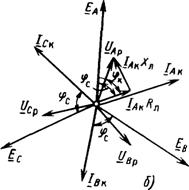 |
Fig.1.4. Triphazne CZ: but- Scheme; b- Vector diagram of flow and voltage |
|
Voltage at points Before equal to zero: UАк = UВк = UСк = 0. R(Fig.1.4, but), U AR=I AkRL.K+j I AkHL.K shown on the diagrams (fig.1.4, b) as the sum of the voltage drop in the active support I AkRL move in phase with the vector I Ak, i in reactive opir I AkHL, inserted at 90° shodo I Ak. Vectors will be similarly U
BPі U
CP. Modules (absolute value) U
AP, U
BP,U
CP may have the same values, skin from tsikh vectors in viperedzhaє strum of the same phase per cut φк =arctg(XL.K/RL.K). For a 35 kV power transmission line, the line is 45 - 55 °, 110 kV - 60 - 78 °, 220 kV (one wire at the phase) - 73 - 82 °, 330 kV (two wires at the phase) - 80 - 85 °, 500 kV (three darts at the phase) – 84–87°, 750 kV (chotiri droti at the phase) – 86–88°. More value φk in support of a larger cut of the dart, to that more stretch, less than R.
Z looked at diagrams of three-phase short circuits: 1) vector diagrams of strums and voltages, symmetrical and vrіvnovazheny, because they have a warehouse of reverse and zero sequences; 2) three-phase short circuit is accompanied by a sharp decrease in the short circuit phase voltage(like at the mist of the short circuit, and near the new one). As a result of which K(3)є the most secure poshkodzhennyam for the stability of the parallel robotic energy system and the saving of electricity.
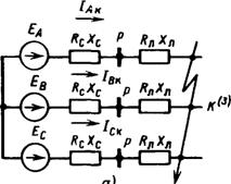
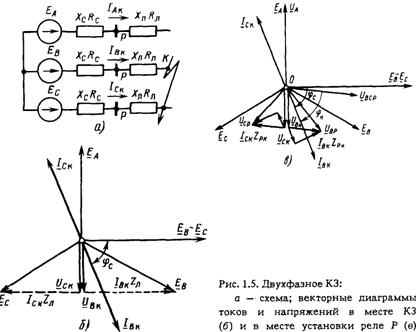
Two-phase short flicker. In Figure 1.5, but shown metal short circuit between phases INі W LEP. Under the direction of interphase EPC EBC(Fig.1.5, but) blame strumi short circuit Ivk taISK.
Їх values are assigned to the formula IК(2)=ЄВС/2ZФ, de 2 ZФ- The latest opir of the direct sequence of two phases ( 2 ZФ=ZВ+ZС). Strums in advanced phases are equal to the values, but prolongations in phase, and strums in non-slow phases are equal to zero (in case of unbalanced pressure):
Strum zero sequence (NP) at K(2) vіdsutnya, to that the sum of strumіv three phases I A+I B+I C=0.
Before. In Figure 1.5, b inducing vectors of phase EPCs and EPCs between alternate phases E ND. Vector strumu kz I kV vidstaє vіd create EPC ![]()
Voltage of non-shocked phase BUT however, whether it is a point of measure and a good phase of the EPC: U A=E A. Oscilki interfacial voltage at metal short circuit at short circuit point U BCk=U Bk - U Cck= 0, then:
Tobto. phase voltage of the ear-shaped phases in the short circuit area is equal to the module and is phase-shifted.
Oskіlki phase voltage in a two-phase short circuit does not avenge warehouse NPs, be it a point of measure, you can be satisfied with your mind:
Vrakhovuychi, what is the mist of KZ U BK=U CKі U AK=E A, known
![]() (1.3b)
(1.3b)
Also, in the case of a short circuit, the voltage of the skin ear phase is more than half the voltage of the non-shock gene phase and it is the same as the sign. On the diagram vector U AK escape vector E A, and the vectors U BKі U CK- equal to one to one and to the length of the phase vector E A.
Dot vector diagram P pointed to Fig.1.5, in. The stream vectors are left without changes. Phase voltages INі W at the point R equal:
What is the point R Vіdstoyat vіd mіstsya KZ, tim more voltage: U BSR= U VR– U SR U AP= E A. Strumu vector I BP Vіdstає vіd interphase voltage U BCP on kut φк=arctg(XL/ RL) .
Two-phase short circuits are characterized by two features:
1) the vectors and strums and the voltages are asymmetrical, but the system is new, what can we say about the presence of warehouse NPs. The presence of non-symmetry shows that the streaks and tensions may have a warehouse sequence (OP) in order from a straight line;
2) the phase voltage in the short circuit area is greater than zero, only one phase voltage is reduced to zero, and the value of the other two is one 1.5 UФ. Therefore, the two-phase short circuit is less unsafe for the stability of the EEC and the saving of electricity.
Single phase short circuit (K(1)). Flickering to the ground one of the phases is calling electric wires 110 kV and more, which can be used with dead-earthed neutrals of transformers. The nature of the strums and stresses that are blamed on the appearance of ushkodzhennia in the phase BUT, Explaining Fig.1.6, but.
Strum KZ Iac what is the fault of the EPC EA, to pass through the slow phase from the dzherel of life G and turn back by earth through grounded neutrals N transformers:
![]() (1.5)
(1.5)
Fig.1.6. Single-phase short circuit:
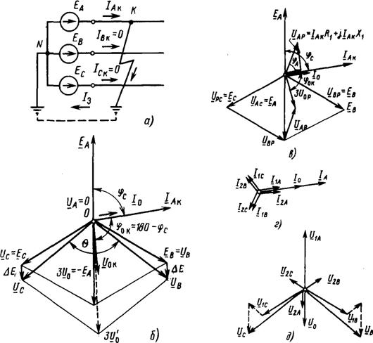
but - scheme; vector diagrams of strum_v and voltage at misc_ short circuit ( b) and in the place where the relay is installed R (in), strumiv ( G) and voltage ( d) symmetrical warehouses
Inductive and active supports in which the phase-to-earth loops show and depend on the value of the phase supports in case of interphase short circuits. Vector I Ak view of the EPC vector EA on kut ![]() In non-shock phases, the struma is daily.
In non-shock phases, the struma is daily.
Voltage of the weak phase BUT at the point Before UAK=0 . Stress of non-shocked phases *2 INі W Rivnі EPC tsikh phases:
![]() (1.6)
(1.6)
The vector diagram of the poshkodzhennya area is shown in Fig. 1.6, b. Interfacial voltage U ABK=U BK; U BCK=U BK-U CK;U CAK=U CK.
Geometric sumi phase streams and voltage equal:
Zvіdsi realized that phase strums and the voltage of the warehouse NP:
![]()
Vector I 0 K zbіgaєtsya on phase z I AK vector U 0 K prolongation in phase E A and more than 1/3 of the normal (up to short circuit) value of the voltage of the ear phase BUT:
U 0 K = - 1/3E A = -1/3U AN. Strum I 0 K viperzhaє strain U 0 K at 90°.
Dot vector diagram R at K(1) is shown in Fig. 1.6, in. Strum phase BUT become immutable. Voltage of the weak phase
Vector U AP viperedzhaє I Ak on kut φк=arctg(Xl(1)/Rl(1)).
Stress of non-shocked phases INі W do not change: U BP=E B; U CP=E C. Interfacial voltage UABPUACP but they get bigger. Vectors NP I 0 Pі U 0 P equal:
Like screaming with diagrams, U op U OK behind the module and shifting in phase through presence active support RKP(1)(Phase-earth). Significantly significant features of vector diagrams (Fig. 1.6, bі in):
1) streams and phases of stresses create an asymmetric and neurological system of vectors, which is to say about the presence of a straight line warehouse VP and NP;
2) phase-to-phase voltage at points Before greater than zero, the area of the tricutnik, set with these tensions, is blown up like zero. Single-phase short circuit є least with a careless look poshkodzhennya with a glance of the stability of the EEC and the robots of the spozhivachiv.
Two phase short circuit to ground(K(1,1)). This type of short circuit can also be blamed only in a measure with a dead-earthed neutral (div. Fig. 1.2, G). The vector diagram of the short circuit to the ground of two phases is shown in Fig. 1.7 for the points Beforeі R.
Under the direction of EPC E INі E W in advanced phases INі W
Strumi flow I VCі I Sk that flicker through the ground:
![]() (1.8)
(1.8)
In non-shocked phase, the strum is daily:
The sum of all three phases with adjustments (1.8) and (1.9) is not equal to zero: I Ak+I Vk+I Sk=I K(3)=3I 0 , return stream revenge on the warehouse of NP.
At mistsі short circuit voltages of low phases INі W, shorted to ground, equal to zero: UBK=UCK = 0. The voltage between variable phases is also equal to zero: UBCK=0. Voltage of non-shocked phase UAK become overwhelmed by normal I VCі I Sk). At the point Before tricot interphase voltage (Fig. 1.7, in) is converted to a line, and the interphase voltage is between weak and non-early phases U ABі U CA decrease to phase voltage U AK.. Strum diagram and voltage for a point R prompted in Fig.1.7, b.
Have a link from the big voltages UBRі UCP increase and interphase voltage, increase the area of tricot interphase voltage and change the voltage NP:
![]()
Fig.1.7. Two-phase short circuit to earth:
but- Scheme; vector diagrams of the stream and the voltage at the short circuit and at the relay installed R (b); zero-sequence voltages and phase voltages at the short circuit area ( in) and to the point R (G)
Vector diagrams in case of two-phase short circuits to the ground, there are such features:
1) streaks and stresses are asymmetrical and neuro-innovative, which will make the appearance of a straight line warehouse NP and VP;
2) through a sharp decrease in the voltage at the short-circuit zone, which type of short-term power supply K (3) is the most important for the stability of the energy system and the saving of electricity.
Underground humming of the earth (K(1)). Similar short circuit is blamed in the measure from the insulated or grounded neutral through the arc reactor. Under the influence of the flickering, it is possible to avoid the flickering to the ground of two phases different points merezhі (K1і K2 in Fig. 1.8). Pіd dієyu raznіtі EPC poshkodzhenikh phases E IN-E W at the phases INі W blame strum K3 I VCі I Sk, which flicker through the ground at points K1і K2. At these points and at the later phases of the stream, the short circuit is equal for the values and prolongation for the phase: I Vk =-
I Sk; non-early phase A strum I AK = 0.
A vector diagram of the streams on the distance between the dzherelom of life and the nearest city of life (dot K1) will be the same as with a two-phase short circuit without earth (div. § 1.3, fig. 1.5). The sum of the strum phases on the ts_y dilanci is equal to zero ( I Ak+I Vk =I Sk=0), also, the streams of the phases have daily warehouses NP.
On the distance of the power transmission line between the points of the mic to the ground K1і K2 in the minds of a one-sided life, the strum of a short circuit flows through only one phase (phase IN in Fig. 1.8), then. so it goes, yak і for a single-phase short circuit (div. § 1.3). The vector diagram of the external streams and the voltage on the second gap is similar to the diagrams for single-phase short circuits (div. Fig. 1.6, b EPC mutual induction increases the voltage of the non-shocked phases and changes the coupling between the phases between them (0 Δ E don't worry.
With single-phase short circuits, the symmetry of the stream and voltage three-phase system break down. On the basis of the method of symmetrical warehouse, asymmetric single-phase short circuits are replaced by three-phase mentally symmetrical short circuits for symmetrical warehouse different sequences. The jet of a single-phase short circuit is composed of three storage sequences - straight (I 1), reverse (I 2) and zero (I 0) sequences. Opіr elemenіv also add up from the support lines (R 1 , X 1 , Z 1), reverse (R 2 , X 2 , Z 2) and zero sequences (R 0 , X 0 , Z 0). Crimea electrical machines support of direct and reverse sequences for elements equal to each other (R 1 \u003d R 2, X 1 \u003d X 2) and equal to their values at a three-phase short circuit. Opir zero sequence ring out signifi- cantly more supports direct and pivotal sequences. In practical roses, take for three-core cables: ; for busbars: ![]() [L.7]; for repeated lines: ; [L.4].
[L.7]; for repeated lines: ; [L.4].
For power transformers, to design the winding circuit D ¤ Y n, opir zero-sequence to direct-sequence supports. For transformers, to change the winding circuit Y ¤ Y to zero sequence support, it is necessary to reverse the direct sequence support.
Single-phase short-circuit strum to indicate:
Here: - The average nominal voltage is measured, in which it became a short circuit (400 V); - Outside the resulting opir of the zero sequence of the short circuit point, mOhm.
The resulting opir of the lancet short circuit is indicated, mOhm:
Here: - Equivalent inductive operation of the call system to the revitalizing transformer 6-10 / 0.4 kV, reduction to the PN stage, mOhm;
- Opir direct sequence step-down transformer, mOhm;
- Opir reactor, mOhm;
- Opir busbar, mOhm;
- Opir cable lines, mΩ;
- Opir of repeated lines, mOm;
- Opir strum coils automatic vimics, mΩ;
- Opіr transformerіv struma, mOhm;
- transitional support of non-robust contact circuits and roaming contacts, transitional support of the arc at the short circuit, mOhm;
- Opir zero sequence of the step-down transformer, mOhm;
- Opir zero sequence of busbars, mOm;
– active and inductive support of zero sequence cable, mOhm;
- Opir zero sequence redundant lines, mOhm.
For a given system of electrical supply (Fig. 4), it is necessary to determine the magnitude of the periodic stream for given points at three-phase and single-phase short circuits (using the symmetrical storage method).
Fig.4. Rozrakhunkov scheme and substitution scheme
1. Behind the rozrachunk scheme, we put together a substitution scheme (Fig. 4).
2. We know the support of the elements of the lancet short-terminated in the names of the units (mOhm).
2.1. Inductive support of the call system up to the live transformer 10/0.4 kV (lances high voltage) (because the intensity of the short circuit on the high side of the transformer is not possible, then it can be accepted).
![]() ; mΩ.
; mΩ.
2.2. Active and inductive support of the energizing transformer (opir of the direct and reversible sequence: ![]() , ; the support of the zero point-
, ; the support of the zero point-
range: , ) [L. 7]:
2.3. Opir busbar 0.4 kV.
For flat busbars with a diameter of 80 x 10 mm (with an average geometric distance between the phases of 15 cm) streak for the direct and pivotal sequence equal, [L.6]. For zero sequence [L.7]:
Active and inductive support of three busbars 0.4 kV direct, return and zero sequences:
Sumarni supports of all three busbars:
2.4. Active and inductive cable supports.
Pets active and inductive supports of individual cables of straight, reverse and zero sequences (methodological instructions):
The values of active and inductive cable supports:
2.5. Active and inductive bearings of automatic switches (including bearings of blast coils and switching bearings of contacts) [L.7].
Sumarni support of all automatic machines:
3. Strum of a single-phase short circuit for the point "K 1".
The results of the active and inductive support of the lance of a short flicker with a single-phase short circuit at the point “K 1”:
Strum of a single-phase short circuit at the point "K 1":
4. Strum of a three-phase short circuit for the point "K 1".
The resulting active and inductive opir of the lance of a short circuit in a three-phase short circuit at the point “K 1”:
Strum of a three-phase short circuit at the point "K 1":
4. Kerіvnі vkazіvki schodo rozrahunku strumіv short zamikannya and vyboru elektroobdnannya. / Ed. B.M. Neklepaev. - M.: View. NTs ENAS, 2001. - 152 p.
5.Kulikov Yu.A. Transitions in electrical systems. / Yu.A. Kulikov. - Novosibirsk: Publishing House of NDTU, 2002. - 283 p.
6. Dovіdnik z designing of electric power supply, line power transmission and metering. / Ed. Ya.M. Bolshama, V.I. Krupovich, M.L. Samovira. View. 2nd, Rev. that dod. - M.: Energia, 1974. - 696 p.
7. Dovіdnik іz proektuvannya elektroprostachannya. / Ed. SOUTH. Barybina and in. - M: Energoatomizdat, 1990. - 576 p.
8. Dovіdnik z electrosupply industrial enterprises. / Zag. ed. A.A. Fedorova and G.V. Serbinovsky. At 2 books. Book 1. Design and development reports. - M.: Energia, 1973. - 520 p.
9. Rules for the installation of electrical installations. - 6th kind. - St. Petersburg: Dean, 1999. - 924 p.
ADDITION A


