Pythomium active and reactive opir midi. Active Opir
Most of all, you can consider that the parameters of the power transmission line (active and reactive support, active and electrical conductance) are equally divided for її dozhina. For a line of relatively small longevity, the separation of parameters can not be corrected and vikoristovuvat zoseredzheni parameters: active and reactive support of the line Rl і Xl, active and єmnіsnu conductance of the line Gl and Bl.
Switch the power transmission lines with a voltage of 110 kV and more up to 300 - 400 km long, sound with a P-like substitution scheme (Fig. 3.1).
The active line opir is assigned to the following formula:
Rl=roL,(3.1)de
ro - pitomy opir, Ohm/km, for wire temperature +20°С;
L is the length of the line, km.
Pitomy opir g0 appears behind the tables as a fallow in the form of a transverse cut. At a temperature of drotu, vіdmіnnoї vіd 200С, opіr lines are specified.
The reactive opir is designated as follows:
Xl=xoL,(3.2)
de xo – reactive opir, Ohm/km.
Pitomy inductive supports of the phases of the reversed line at a different angle. With rosary symmetrical modes vicorate the average value of xo:
![]()
de rpr - radius of the dart, cm;
Dav - geometric mean between phases, cm
de Dab, Dbc, Dca – between the filaments in phases a, b, c, Fig. 3.2.
When parallel lancets are placed on double lancets, the flow chain of the cutaneous phase drota is marked by strumas of both lances. Change xo through the injection of another lancer into the Persian black, lie down in the middle of the lancers. Vіdminnist x of one lancer with the appearance and without urakhuvannya inflow of another lancer does not outweigh 5-6% and is not insured with practical roses.
At power lines with Unom ZZ0kV, the wires of the skin phase are split into sprat (N) wires. Tse vіdpovidaє zbіlshennyu equivalent radius. Equivalent radius of split phase:
de a - stand between the wires at the phase.
For steel-aluminum wires, xo is assigned to the final tables depending on the number of wires in the phase.
Active line conduction active tension: strum a coil through the insulator and onto the crown.
Strumi a coil through the insulators and small, that with the straining in the insulators you can suffocate. At the redundant lines with a voltage of 110 kV and above the singing minds, the electric field strength on the surface increases and becomes more critical. Seen near the dart, it intensely ionizes, making the candle shine - the crown. The crown wears out active tightness. The most radical way to reduce the amount of pressure on the crown is to increase the diameter of the crown. Smallest allowable wire cuts repeated lines normalized for the minds of the crown: 110kV - 70 mm2; 220kV -240 mm2; 330kV -2x240 mm2; 500kV - 3x300 mm2; 750kV - 4x400 or 5x240 mm2.
When rebuilding the installed modes electrical tethers voltage up to 220 kV active conduction is practically not protected. In meshes with Unom³ЗЗ0kV in case of prescribed straining and in case of rozrahunku optimal modes it is necessary to pay for the crown:
DPk = DPk0L=U2g0L,3.6)
de DPk0 – no active pressure on the crown, g0 – no active conduction.
The capacity of the line Bl is equipped with capacities between the wires of different phases and the capacity of the conductor - earth and is indicated as follows:
de bo - pet єmnіsna provіdnіst, Sm / km, as can be assigned to the dovіdkovyh tables or for this formula:
![]()
The greater number of expansions at the 110-220 kV lines, the power transmission line sounds like a simple substitution scheme (Fig. 3.3, b). In this scheme, the replacement of the multiplicity of conduction (Fig. 3.3, a) is protected by reactive strain, which is generated by the multiplier lines. Half of the єmnіsnoї (charging) tightness of the line, Mvar, dorіvnyuє:
UФ and U – phase and interphase voltage, kV;
Ib - єmnіsny strum on the ground.
![]()
![]()
Rice. 3.3. Substitution schemes for power transmission lines:
a b - repeated line 110-220-330 kV;
c - repeated line Unom 35 kV;
g - cable line Unom £10 kV
Z (3.8) next, that the tension Qb, which is generated by the line, is strongly deposited in the voltage. For broken lines with a voltage of 35 kV and lower voltage, it is possible not to damage (Fig. 3.3, c). For lines Unom ³ ЗЗ0 kV with a length of over 300-400 km, it is necessary to insure equal support and conductance of the line. The substitution scheme for such lines is a chotiripoleum.
Cable lines of power transmission also have a P-like substitution scheme. Pets active and reactive supports ro, xo are assigned to the final tables, like for redundant lines. From (3.3), (3.7) it can be seen that xo changes, and bo increases when the phase conductors are close. For cable lines between conductors, it is significantly less, lower for repeaters, it is not enough, and when changing modes for cable lines with a voltage of 10 kV, and lower, it is possible to protect only active opir (Fig. 3.3, d). Surge and charge pressure Qb cable lines more, lower at the repeaters. At cable lines high voltage vrakhovuyut Qb (Fig. 3.3 b). Active conduction Gl is safe for cables 110 kV and more.
3.2. Spend the tightness in the lines
Spend active pressure in the power line to spend on idling DРХХ (spend on the crown) and spend on heating (on heating the wires) DРН:
Spend at the lines reactive pressure stained on the alignment of the magnetic flux in the middle and next to the dart ![]()
Obumovlyuє heating of wires (thermal losses) and laying in the material of the strum-conducting conductors and their peretina. For lines with wires of a small overlap, rimmed with colored metal (aluminum, copper), the active opir is taken equal to the ohmic one (opir of the post-strum), the shards showing the surface effect at industrial frequencies of 50-60 Hz are imperceptible (about 1%). For darts with a large cut (500 mm and more), the appearance of a surface effect at industrial frequencies is significant
Active extinction of the line depends on the formula, Ohm / km
de - pitomium active opir material drot, Ohm mm/km; F- cutting the phase wire (lived), . For technical aluminum in the fallow type, the grade can be taken = 295-315 ohm mm / km for midi = 180-190 ohm mm 2 / km.
The active opir does not become immutable. It is necessary to lie down in the temperature of the dart, as it is indicated by the temperature of the superfluous wind (middle), swidkistyu wind and the value of the stream, which is to pass through the dart.
Omіchne opіr can be simply interpreted as a shift to the straightened ruh of the charges in the crystal lattice to the material of the conductor, which induces kolivny ruhi at an evenly important station. The intensity of the cracking and the ohmic opir increase according to the increase in the temperature of the conductor.
fallow active support according to temperature t stand out at the sight
de- normative value support R 0 is secured by the formula (4.2) , for conductor temperature t= 20°C; a - temperature coefficient electrical support, Ohm/deg (for copper, aluminum and steel-aluminum wires α = 0.00403, for steel α = 0.00405).
The difficulty of clarifying the active support line (4.3) is due to the fact that the temperature strum advancement that intensity of cooling, can slightly overestimate the temperature of the superfluous middle. The need for such a clarification can be blamed on the re-exploration of seasonal electric modes.
When splitting the PL phase into n the same darts at the bend (4.2) it is necessary to protect the total phase wire cut:
4.2. Inductive Opir
Zoomed in by a magnetic field, which causes a lot of damage in the middle of the conductor when passing through it snake struma. At the conductor, EPC self-induction is induced, it is straight-lined to the Lenz principle in the same direction as EPC dzherel
![]()
Protidia, how to repair EPC self-induction change EPC dzherel, that inductive support of the conductor. What is the greater change in the flow chain, which is determined by the frequency of the struma = 2nf di/dt), and the value of the inductance of the phase L, which should lie in the design (decoupling) of the phase, and the three-phase power transmission line in general, there is more inductive support of the element X \u003d L. Tobto for one ієї і ієї zh linії (or just the electric jet frequency of the coil) zі inductive opir zbіlshuєtsya. Naturally, with zero frequency = 2nf = 0, for example, at the lines fast strumu, inductive opir LEP daily
On the inductive support of the phases of the rich-phase power transmission lines, the same mutual roztashuvannya phase darts (lived). Cream of EPC self-induction, at the skin phase, antidote and EPC of mutual induction are induced. Therefore, with a symmetrical expansion of the phases, for example, along the tops of an equal-sided tricot, the resulting EPC in all phases is the same, and also, the same proportional and inductive support of the phases. With horizontal expansion of the phase wires, the flux linkage of the phases is not the same, so the inductive supports of the phase wires are blown into each other. To achieve symmetry (sameness) of phase parameters on special supports, transposition (rearrangement) of phase darts is made.
Inductive opir, insertion up to 1 km of the line, depends on the empirical formula, Ohm / km,
If we take a struma frequency of 50 Hz, then when the frequency is set to = 2nf = 314 rad / s for darts made of color metals (|m = 1), it is taken, Ohm / km,
However, for submarines rated voltage characteristic spіvvіdnosnja mizh parameters R0<
![]() (4.23)
(4.23)
![]()
de a - cut between the wires at the phase, which is 40-60 cm long.
The fallow analysis (4.23) shows that the equivalent shows that the equivalent phase radius changes in the range of 9.3 cm (at n= 2) up to 65 cm (with n\u003d 10) and it is not enough to lie in front of the dart. The main factor that determines the change is the number of wires in the phase. Since the equivalent radius of the split phase is larger than the nominal radius of the non-split phase, then inductively
Opir such a submarine, which is assigned to the converted formula of the form (4.24), Ohm / km, changes:
![]() (4.24)
(4.24)
The decrease in X 0 is reached mainly for the change in the level of the support X "0, but it is not large.
Increasing the building capacity (ideal boundary) of the line:
![]() (4.25)
(4.25)
Naturally, with an increase in the equivalent radius of the phase, the electric field strength around the phase decreases, therefore, expend more effort on the coronation. Prote total values of these inputs for high-voltage and superhigh-voltage submarines (220 kV and more) add up the observed values, the appearance of any necessary in the analysis of the regimes in the linear designations of the stress classes ( Rice. 4.5).
The splitting of the phase into a sprig of wires with a larger capacity of the submarine and a higher capacity of the submarine:
![]() (4.26)
(4.26)
For example, when splitting the phase of a 220 kV submarine into two strands, the conductivity increases from 2.7 10 -6 to 3.5 10 -6 S/km. Todi charging capacity of a 220 kV submarine of average length, for example 200 km, to become
what can be compared with the transmitted tensions according to the PL of a given class of tension, the cream with the natural tension of the line
![]() (4.27)
(4.27)
4.6. Substitution schemes for power transmission lines
The characteristic of other elements of line substitution schemes has been given more. Vidpovidno to their physical manifestation when modeling electrical circuits, wiring diagrams of PL, CL and busbars, presented on Rice. 4.5, Rice. 4.6, Rice. 4.7. Let's bring some more detailed explanations to these schemes.
When expanding the symmetrical modes in the EU, the substitution circuit is established for one phase, then the later parameters, the support Z = R + JX is shown and calculated for one phase wire (core), and when the phase is split, the number of wires in the phase is equal to the equivalent phase radius. PL.
Єmnіsna prіdnіstі Vs, vrakhovuє provіdnostі (ємnostі) between phases, between phases and the earth and in vіdobrazhaє generation of charging pressure of all three-phase construction lines:
![]()
Active line capacity g, what is displayed at the shunt between the phase (living) and the point of zero potential of the circuit (earth), including the total amount of active strain on the crown (or in isolation) of three phases:
Transverse conductivity (shunts) Y=G+jX in substitution schemes, you can not depict, but replace the shunts with strains ( Rice. 4.5 b; Rice. 4.6, b ). For example, instead of active conductivity, show the consumption of active tension of the PL:
![]() (4.29)
(4.29)
or in CL insulation:
The replacement of the electrical conductivity indicates the generation of the charging pressure
![]() (4.30a)
(4.30a)
The designations of the shape of the transverse beams of the power transmission line are designed to simplify the assessment of electrical modes, which are manually adjusted. Such schemes of substitution of lines are called rozrachunk ( Rice. 4.5 b; Rice. 4.6, b).
At power transmission lines with a voltage of up to 220 kV, for singing minds, it is possible not to protect those other parameters, as if they were pouring into the work of the carriers. U zv'yazku z tsim line substitution schemes shown on Rice. 4.1, you can be asked for an hour.
For submarines with a voltage of up to 220 kV, apply pressure to the crown, and for a cable with a voltage of up to 35 kV, the electric power is negligible. Therefore, in the distribution of electrical modes, they do not have and take active conductivity equal to zero ( Rice. 4.6). The form of active conduction is necessary for a PL with a voltage of 220 kV and for a CL with a voltage of 110 kV and more in the distribution of electric power, and a PL with a voltage of 330 kV and more so with the distribution of electrical modes ( Rice. 4.5).
It is necessary for the appearance of the capacity and the charging tension of the line to lie in the presence of the totality of the charge and the tension tension. In the case of small chains with rated voltages up to 35 kV, the charging jet and tension are significantly less than the navantage. Therefore, in the CL, it is possible to protect the conductivity only at voltages of 20 and 35 kV, and the submarine can be protected by it.
At district fencing (110 kV and more) with significant lengths (40-50 km and more), the charge intensity can be combined with the navantage and add to the overall appearance or without middle ( Rice. 4.6, b) or for the needs of lower conductivities ( Rice. 4.6, a).
At the wires of the submarine with small gaps (16-35 mm 2), the active supports are overridden, and for large gaps (240 mm 2 at the district lines with a voltage of 220 kV and more), the power of the line is indicated by their inductances. The active and inductive supports of the wires of the middle overshoots (50-185 mm2) are close to one to one. For cable lines with a voltage of up to 10 kV, small overshoots (50 mm 2 and less) are initially active, and in this case, inductive supports may not be damaged ( Rice. 4.7b).
The need for the appearance of inductive supports is also to be deposited in part of the reactive storage stream near the hot electric supply. When analyzing electrical modes with low pressure coefficients (cos<0,8) индуктивные сопротивления КЛ необходимо учитывать. В противном случае возможны ошибки, приводящие к уменьшению действительной величины потери напряжения.
The replacement schemes for the LEP of a permanent stream can be seen as a series of substitution schemes for the LEP of a permanent stream at X = 0 i b = 0.
Placed on 01/10/2012 (valid until 04/10/2013)
The line of the electric line is theoretically considered to be such that it consists of an infinitely large number of equally divided links of active and reactive supports and conductors.
The exact shape of the inflow of rozpodіlenih supports and ductility of folds and is necessary for the expansion of the arches of long lines, as it is not seen at this course.
In practice, they are intermingled with simpler methods of rozrahunka, looking at the line of active and reactive supports and conductions.
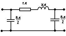
To carry out the survey, a simple line substitution scheme is used, but at the same time: P-similar substitution scheme, which is made up of successively active (r l) and reactive (x l) supports. Active (g l) and reactive (mnisna) (b l) conductivity included on the cob and in the end of the line by 1/2.
P-similar substitution scheme and at the overhead power transmission lines with a voltage of 110-220 kV with a length of up to 300-400 km.
The active opir is assigned to the following formula:
r l \u003d r pro ∙l,
de r pro - Pitomy opіr Om / km at t about darts + 20 pro, l - Dovzhina line, km.
The active support of wires and cables at a frequency of 50 Hz sounds approximately the same as the resistance support. Chi is not protected by the manifestation of the superficial effect.
Pythomium active opir r about steel-aluminum and other darts from color metals is shown behind the tables as a fallow in the form of a transverse cut.
For steel darts, the surface effect cannot be harmed. For them, r about to lie in the overflow and struma, what flows through, and to be known from the tables.
At a temperature of drotu, vіdmіnnoї vіd 20 o C opіr lines are specified according to the relevant formulas.
The reactive opir is indicated by:
x l \u003d x pro ∙l,
de x pro - pithomium reactive opir ohm/km.
Pitomy inductive supports of the phases of the submarine at the wild slope are different. When symmetrical regimes are expanded, the average value of x:
de r pr is the radius of the dot, cm;
D av - geometric mean between phases, div is determined by the oncoming virase:
D av = (D AV D AV D SA) 1/3
De D AB, D AB, D SA - between wires in phases A, B, C.
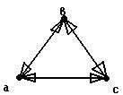
For example, when the phases are expanded along the corners of an equal-sided tricot fabric on the side D, the middle geometrical line is more expensive D.
D AB = D BC = D SA = D
When placing the wires of the power transmission line in a horizontal position:
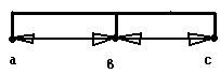
D AB = D BC = D
D SA \u003d 2D
When parallel lancets are placed on double lancets, the flow chain of the cutaneous phase drota is marked by strumas of both lances. Replacing X 0 through the inflow of another lancet, lie down in the middle of the lances. Vіdmіnіst X 0 of one lancer, with the appearance of one without urahuvannya, the inflow of another lancer does not exceed 5-6% and is not protected by practical roses.
At power lines at U nom ≥330 kV (inode and at voltage 110 and 220 kV), the wires of the skin phase are split into sprats. Tse vіdpovidaє zbіlshennyu equivalent radius. Virase for X0:
X pro \u003d 0.144lg (D cf / r pr) + 0.0157 (1)
deputy r pr victorious
r ek \u003d (r pr a cf pf-1) 1 / pF,
de r ek is the equivalent radius of the dot, cm;
a cf is the mean geometric distance between the wires of one phase, cm;
n f is the number of wires in one phase.
For a line with split wires, the remaining additions in formula 1 are changed by n phrases, tobto. may look 0.0157/n f.
Pithomium active opir phase lines with split wires are designated as follows:
r 0 \u003d r 0pr / n f,
de r 0pr - pitomy opir drotu this review, appointments for dovidkovy tables.
For steel-aluminum wires X 0 is assigned to the final tables, fallow in cut, for steel fallow in cut and struma.
Active conduction (g l) lines indicative of two types of active tension insertion:
1) strumming the coil through the insulators;
2) spend the crown.
Strumi a coil through the insulators (TF-20) is small and in the insulators can be broken. At the redundant lines (PL) with a voltage of 110 kV and more for singing minds, the electric field strength on the surface increases and becomes more critical. Seen near the dart, it intensely ionizes, making the candle shine - the crown. The crown wears out active tightness. The most radical means of changing the pressure on the crown is to increase the diameter of the dart, for a high voltage line (330 kV and more) the splitting of the dart. Sometimes you can win the titles as a systemic way to change the cost of the crown. The dispatcher changes the line voltage to the same value.
At the link with the cym, the smallest allowable cuts with a crown are given:
150 kV - 120 mm 2;
220 kV - 240 mm2.
Coronation of wires to direct:
Before lowering the KKD,
Until the hardened oxidation of the surface of the darts,
Until the advent of the radio code.
When rozrahunku regimes in merezh, which have been established, up to 220 kV active conduction is practically not protected.
In tethers with U nom ≥330 kV, with a prescribed amount of tension during the development of optimal modes, it is necessary to insure the cost of the crown.
The capacity (in l) of the line is lined with capacities between the wires of different phases and the capacity of the conductor - earth and is indicated as follows:
in l = 0 l,
de to 0 - pet єmnіsna provіdnіst Sm / km, which can be assigned to the pre-test tables, or to this formula:
y 0 \u003d 7.58 ∙ 10- 6 / lg (D cf / r pr) (2),
de D cf - geometric mean between the wires of the phases; r pr is the radius of the dart.
For more rozrahunkiv at the lines of 110-220 kV power transmission lines (power lines) with a simple replacement scheme:
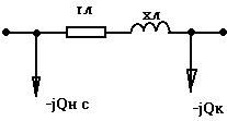
In some cases, the substitution circuit replaces the mnistane conductivity in l / 2, the reactive pressure is protected, which is generated by the mnist of the lines (charging tension).
Half of the ½mnіsnoї tightness of the line, MVAr, dorіvnyuє:
Q C \u003d 3I c U f \u003d 3U f 0 l / 2 \u003d 0.5V 2 in l, (*),
de U f і U - vіdpovіdno phase and interfazne (linear) voltage, kV;
I with - єmnіsny strum on the ground:
Ic \u003d U f in l / 2
From the point of view of Q C (*) it is obvious that the straining of Q C, which is generated by lines strongly deposited in the stress. The greater the voltage, the greater the tension.
For reinforced lines with a voltage of 35 kV and lower voltage intensities (Q C) can not be damaged, even though the replacement circuit should look ahead:
For lines with U nom ≥330 kV with a length of more than 300-400 km, it is necessary to insure even rozpodil supports and conductivities of the line.
Cable lines of power transmission have the same P-like substitution scheme as PL.
Pets active and reactive supports r 0 x 0 are assigned to the final tables, as well as for submarines.
3 virase for X 0 and 0:
X pro \u003d 0.144lg (D povn / r pr) + 0.0157
y 0 \u003d 7.58 ∙ 10 -6 / lg (D cf / r pr)
it can be seen that X 0 changes, and 0 grows when different wires are close.
For cable lines, the phases between wires are significantly less, lower for PL і Х 0 is even less.
When changing the modes of cable lines (cable lines) with a voltage of 10 kV and lower, it is possible to protect only active opir.
Єmnіsny strum і Q C cable lines have more lower PL. In cable lines (CL), high voltages are reversed Q C , moreover, the small tension Q C0 kvar / km can be calculated from the tables at the dovidniks.
Active conductivity (g l) must be paid for cables 110 kV and higher.
The parameters of the cables X 0 and Q C0 are indicated in the preliminary tables of orientation, more precisely they can be determined by the factory characteristics of the cables.
| Talk on the forum |
|
| |
|
The phase parameters of power transmission lines are evenly divided into її dozhinі, tobto. power transmission line with a lancet with equally spaced parameters. Accurate analysis of the scheme, to avenge such a lance, to bring it to a foldable calculation. At zv'yazku z tsimp pіd h rozrahunka linіy elektrotransmissions at vypadku zastosovuyut simple "T" and "P" -shaped substitution schemes іz zoseredzhennymi parameters (figure No. 1). The breaks of the electric line rozrahunka at “T” and “P” - similar substitution schemes are approximately the same. The stench is to lie down in the old line.
The assumption about the importance of the real equal distribution of parameters according to the length of the power transmission line is valid for the length of repeated lines (PL), which does not exceed 300-350 km, and for cable lines (CL) 50-60 km. For the LEP of the Great Dozhina, it is necessary to work out different ways and shape the difference between their parameters.
The size of the EU scheme and, accordingly, the system of modeling equalities, is determined by the number of the scheme. Also, in practical, rozrakhunka, especially with EOM victories, most often vicorists use “P” - a figurative replacement scheme, but one advantage - less 1.5 times the size of the scheme against the modeling of the LEP “T” - a figurative scheme. For this reason, there is a further contribution to be made in the form of a “P” - a figurative scheme for replacing the LEP.
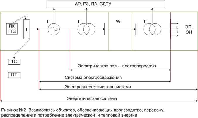
It can be seen in the substitution schemes of the later elements - the support of the power transmission line Z=R+jX and the transverse elements - the conductivity Y=G+jB (Figure No. 2). The values of the assigned parameters for the LEP are assigned for the main factor
de P (R 0, X 0, g 0, b 0) - the value of the later or transverse parameter, introduced up to 1 km of the line L, km. Other parameters are called chase.
For a power transmission line of a particular class, the voltage of the vicorous voltage fluctuates frequently in their circuits, depending on the physical manifestation of the magnitude (value) of the type parameter. Let's look briefly at the essence of these parameters.
Active support for heating wires (thermal losses) and laying in the material of the streak-conducting conductors and their cross-section. For lines with small wires, which are marked with colored metal (aluminum, copper), the active opir is taken equal to the ohmic one (opir to the constant stream), the shards showing the surface effect at industrial frequencies of 50-60 Hz are not noticeable (about 1%). For large conductors (500 mm 2 and more), the surface effect at industrial frequencies is significant.
The active line reference is determined by the formula Ohm/km,
de; - Pitomy active opir material drotu, Ohm mm 2 /km; F-overlap of the phase wire (lived), mm 2. For technical aluminum, fallow of the first grade, can be accepted; \u003d 29.5-31.5 Omm 2 / km, for midi; \u003d 18-19 Ommm 2 / km.
The active opir does not become immutable. It is necessary to lie down in the temperature of the dart, as it is indicated by the temperature of the superfluous wind (middle), the wind speed and the value of the stream, which is to pass through the dart.
Om_chny opir can be simply interpreted as a shift to a straight-lined rush of charges in the crystalline cores of the material of the conductor, which will create a pounding ruhi of an equal-important state. The intensity of the cracking and, vidpovidno, ohmichny opir grows according to the increase in the temperature of the conductor.
The deposit of the active support in the temperature of the core t is shown as
de - the normative value of the support R 0 is opened according to the formula No. 2, at the temperature of the conductor t = 20 0 С; α-temperature coefficient of electric support, Ohm/deg (for copper, aluminium, and steel-aluminum wires α=0.00403, for steel α=0.00455).
The importance of clarifying the active support of the line for formula No. 3 is due to the fact that the temperature is different, that it should lie in the stream pressure and the intensity of cooling, you can slightly change the temperature dovkilla. The need for such a clarification may be due to the hour of the re-roofing of seasonal electric modes.
When splitting the phase of the PL into n identical wires in virus No. 2, it is necessary to repair the total cut of the wires of the phase:
The inductive opir is surrounded by a magnetic field, which causes it to be near and in the middle of the conductor when the struma passes through. At the conductor, EPC self-induction is induced, straightened according to the Lenz principle, similar to EPC dzherel
![]()
Protidiya, yak nada EPC self-induction change EPC dzherel, that inductive support of the conductor. How to change the flux linkage, which depends on the frequency of the stream; f (change the stream of di / dt), and the value of the inductance of the phase L to lie in the design (decoupling) of the phase and the three-phase power transmission line as a whole, there is more inductive support of the element Х=ωL. Tobto for odnієї i tієї zh linії (or just an electric coil) with increasing frequency of the struma f іnductivny opіr zbіlshuєtsya. Naturally, scho z zero frequency (;f=0), for example, at the fences of the steady stream, the inductive support of the LEP is daily.
On the inductive support of the phases of the rich-phase power transmission lines, it is also injected into the mutual expansion of the phase darts (cores). Cream of EPC self-induction, at the skin phase, antidote and EPC of mutual induction are induced. Therefore, with a symmetrical expansion of the phases, for example, along the tops of an equal-sided tricot, resulting in the opposite ELS in all phases is the same, and also, the same proportional and inductive support of the phases. With horizontal expansion of the phase wires, the flux linkage of the phases is not the same, so the inductive supports of the phase wires wind one type of one. To achieve symmetry (sameness) of phase parameters on special supports, transposition (rearrangement) of phase darts is made.
Inductive opir, insertion up to 1 km of the line, depends on the empirical formula, Ohm / km,
![]() (5)
(5)
If you take the frequency of the struma 50 Hz, then when the frequency is set;
![]() (6)
(6)
and at a frequency of 60 Hz it is clear (ω=376.8 rad/s), Ohm/km
![]() (7)
(7)
When the phase wires are close together, the EPC mutual inductance increases, which leads to a change in the inductive support of the power transmission line. Particularly noteworthy is the reduction of the inductive support (3-5 times) for cable lines. The compact submarines of high and supra-high voltages increased throughput building with 25-20% convergence by inductive support were disassembled.
The value of the geometric mean distance between the phase wires (cores), m,
![]() (8)
(8)
lie in the field of roztashuvannya phase darts (tires). The phases of the submarine can be laid out horizontally or along the tops of the tricout, the phases of the strum duct bus at the horizontal or vertical plane, lived in a three-wire cable - along the tops of the equal-sided tricout. The value of D cf and r pr due to the mother of the same rozmіrnіst.
For the number of pre-existing data, the actual radius of the rich wire wires r can be calculated for the total area of the cross section of the steel wire and the steel part of the wire, increasing it by 15 - 20%, tobto.
![]() (9)
(9)
It is significant that the inductive opir is composed of two warehouses: external and internal. The outer inductive opir is determined by the outer magnetic flux, which is determined by the wires, and the values of D SR and r PR. Zrozumіlo, scho zmenshennyam vіdstanі mіzh phases zrostaє inflow of EPC mutually inductive and inductive support decreases, and navpaki. In cable lines with small distances between current-carrying cores (two orders of magnitude less, lower for submarines), the inductive support is significantly (3-5 times) less, lower for repeaters. For designation X 0 cable lines No. 5 and No. 6 do not stop, stink shards do not protect the design features of cables.
That is why, when rozrahunka, they are covered with factory data about the inductive support of cables. The internal inductive opir is indicated by the internal flow, which flickers at the rods.
For steel wires, it is important to deposit in the form of a strum deposit and is given in the dovodkovy literature.
In this way, the active opir of the LEP should be deposited in the material, cutting through the temperature and the core. The fall is turned in proportion to the wire cut, clearly pronounced with small wire cuts, if R 0 can be large, and little marked with large wire cuts. The inductive support of the power transmission line is assigned to the lines, the construction of the phase and it is practically not possible to lie in the gap of the wires (the value of lg (D SR / r PR) ≈ const).
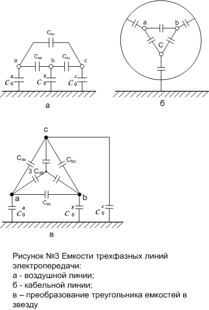
The electrical conductivity is wired with capacities between phases, phase wires (residential) and earth. In the scheme of substitution of the LEP, the rozrahunkov (working) shoulder capacitance of the equivalent zirka is removed, which is removed from the conversion of the tricutnik of conductances to the zirka (Figure No. 3, c).
In practical rozrahunka work, the capacity of a three-phase submarine with one dart per unit of time (F / km) is assigned to the formula
 (10)
(10)
The working capacity of the cable lines is significant for the capacity of the submarines, the shards lived like close friends and grounded with metal shells. In addition, the dielectric penetration of cable insulation is significantly greater per unit - the dielectric penetration of the wind. Great variability of the cable design, the presence of their geometrical dimensions are conveniently assigned to the working capacity, at the connection with which they are practically corroded by the denim of the operational chi of the factory worlds.
Estimated conductivity of PL and CL, Sm/km, depends on the global formula
Table No. 1 Working capacity Z 0 (10 -6), F / km, three-core cables with belt insulation
|
Voltage, kV |
Peretin lived, mm 2 |
||||||||||
To improve viraz No. 10 (a) for the repeated line at the frequency of the struma 50 Hz maєmo, S/km,
 (11)
(11)
and for a submarine with a voltage frequency of 60 Hz, it is taken, Sm / km,
 (12)
(12)
The location of the conductor to lie in the design of the cable and is indicated by the plant-manufacturer, but for the oriental rosettes it can be estimated according to the formula No. 11.
Under the voltage applied to the line, voltages are projected through the line capacities. Todi rozrahunkove value of the final strum per unit of time, kA/km,
![]() (13)
(13)
and charging pressure of a three-phase power transmission line, which indicates power, Mvar/km,
lie down in the tension at the skin point.
The value of the charging tension for all power lines is determined through the effective (rozrahunkov) stress on the cob and the end of the line, Mvar,
or approximately behind the nominal elastic line
For cables 6-35 kV with paper insulation and viscous seepage in the generation of reactive tension q 0 per kilometer of the line,
LEP with transverse electrical conductivity, which spozhivaє z mirezhі viperzhaє napruzhі єmnіsnoї strum, slid to look like a jerelo reactive (inductive) tension, often called the charger. Mayuchi єmnіsny character, charging tension changes the inductive warehouse navantage, which is transmitted to the line to the spozhivach.
In the substitution circuits of the PL, starting from the nominal voltage of 110 kV, and CL-35 kV, it is more necessary to secure the transverse wires (shunts) at the visually small conductivities, or generating strains Q C .
Between the phases of the LEP in the skin class of tension, especially for submarines, it is practically the same, which indicates the invariance of the resulting flow of the phases and the mnemonic effect of the lines, To that for the traditional submarines (without a deep splitting of the phases and special structures of the supports) lines, shards in the transition between the phases and the cross section (radius) of the wires are practically unchanged, which is shown in the guidance formulas with a logarithmic function.
When the phases of the PL 35-220 kV are broken with single wires, the inductive support at narrow boundaries: Х 0 = (0.40-0.44) Ohm / km, and the final conductivity lies at the boundaries b 0 = (2.6-2.8)10 -6 Div/km. Having added a change in the area of the cross section (radius), the cable is alive on X0 more commemorated, lower in the submarine. Therefore, for CL it is possible to change the inductive support more widely: X 0 ≈ (0.06-0.15) Ohm / km. For cable lines of all brands and overvoltage of 0.38-10 kV, the inductive support lies at the upper interval (0.06-0.1 Ohm / km) and it is indicated from the table of physical and technical data of cables.
The average value of the charging intensity per 100 km for a 110 kV submarine is close to 3.5 Mvar, for 220 kV - 13.5 Mvar, for a 500 kV submarine - 95 Mvar.
The appearance of these indications allows you to turn on significant pardons during the development of parameters in the line, or to select the designated parameters in the nearest examinations, for example, to assess the reactive parameters of the submarine її length (km) at sight
The active conductivity is connected with the losses of active sweating ΔР through the lack of insulation (on the surface of the insulators, the conductivity layer (shift) at the material of the insulator) and ionization again on the conductor in the presence of a corona discharge. Pitoma active conductivity depends on the general formula of the shunt, cm / km,
de U nom - nominal voltage of the power transmission line at kV.
The losses in the insulation of the submarine are insignificant, and the appearance of the crowning of the submarine is only blamed for the over-voltage of the electric field against the surface, kV MAX / cm:
the critical value is close to 17-19 kV / div. Such a mind for crowning is blamed on the 110 kV submarine and the higher voltage.
Crowning and, later, in the case of active sweating, lie heavily in the stress of the submarine, the radius of the rod, atmospheric minds, and become the surface of the rod. The greater the working voltage and the smaller radius of the wires, the greater the tension of the electric field. Reduce atmospheric insufficiency (high water content, wet snow, napisto on the surface of the wires), scuffs, undercuts, and also absorb the increase in the electric field tension and, apparently, the inflow of active strain on the corona bath. The corona discharge calls for a switch to radio and television reception, corrosion of the surface wires of the submarine.
To reduce the cost of the corona to an economically acceptable level, the rules for the installation of electrical installations (PUE) set the minimum overshoot (diameter) of the wires. For example, for PL 110kV-AC 70 (11.8 mm), for PL 220 kV-AC 240 (21.6mm).
Spend effort on coronation when simulating submarines with a nominal voltage of 330 kV or more.
At the cable line under the greatest tension, there are balls of belt insulation on the surface of the cable cores. The greater the working voltage of the cable, the more commemorate the flow of a coil through the insulation materials and the destruction of the electrical authorities. The latter are characterized by the tangent of the cut of the electrical inputs tg, which is taken as a tribute to the virobnik plant.
Active cable conduction for one day
![]() (20)
(20)
і v_dpov_dny strum turn in the insulation of the cable, A,
![]() (21)
(21)
Todi dielectric cost of insulation material KL, MW,
Їх слід vrakhovuvati for cable lines with a rated voltage of 110 kV and more.


