"electronics and radio engineering"
"CONTROL" and "PRODZVINKA" for ELECTRICIAN.
Reversing the electrical circuit of the layout in noisy workshops is not easy to manually flicker with mimicry fittings, to be brought to touch the fitting at once, to marvel at this display and to click on the switching mode of the robot. If you want the "RULES FOR SAFE OPERATION OF ELECTRICAL INSTALLATIONS SPOZHIVACHІV" to fuse with control lamps, electricians often, in order to check the correctness of electrical lances, use a simple control lamp, as a vicorist function as a handy and rich function.
If you want, on the right, not in a light bulb, but in someone who is trying - you can screw up and with a voltage indicator and with a trusted attachment, as if you were trying to win in the hands of a harmless practitioner, or someone who is not able to behave with him in a proper rank.
And the axis of visibility with a competent choice of "controls" seems to be for itself:
By the incandescence of the lamp, you can visually estimate the magnitude of the voltage;
The light of the lamp of the roasting is kindly remembered with a bright light;
Zavdyaki low input support, do not give pardons in the case of the induced voltage (“guided”) and “through the tension”;
Allows you to reconsider the lances of zahisnoy zanulennya, the robot (or inaccuracy) ELV, and, to the last, can victorious like a portable light.
For a safe alternative, the control lamp is structurally responsible, but it is placed in a case with insulating material, transparent or through a hole for the passage of a light signal. Providniki Minkni Buti Bentukhi, Nopeyino, I don't use 0.5 m in contact, for the vulvenous zymicannya, for the vulnery of the Zagalnye introduced, send from Armaturi to Rіznі, and on the Vilny Kіntsy Mati Jorstki Elektrodi, shovel by the hands of the Handles, Dovanga Naked Kіntzia Elektrod is not obey shift 10 - 20 mm.
For the preparation of a simple and easy one in the repeated version of the "control": take two lamps 220V 15W for the refrigerator, solder them in series to each other, as conductors, you can vicorate the probes of the multimeter with plastic sacks on the tips, darts in some baganettes. The flanges on such probes protect the possibility of fingers being exposed to the critical ends of the probes and the jet-conducting parts of the installations. Then let's use offensive lamps near the transparent case (for example, near the holes of the transparent hose) and apparently the other name. 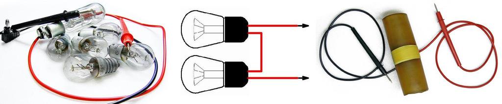
In the process of rechecking the integrity of the wiring, it is necessary to comply with the rules of electrical safety, the “control” may be suspended on the wires, when rechecking is carried out in the vicinity of the log, it is necessary to check in yourself.
PROBE - INDICATOR.
In quiet situations (minds), if it’s easier to speed up with a “control”, and not with an attachment, then in simple schemes for a forward assessment of the functioning of nodes during repairs and upgrades of electrical appliances and electronic attachments, then accuracy is not required. Often you can see a corny probe-indicator, which allows you to designate in lancet, which is reversed:
Availability of variable or constant voltage from 12 to 400V,
Phase drotu in the lancets of a snake strum,
Oriental value of the voltage,
The polarity of the lancets of the post-stromu
Carry out a “pro-call” of the number of lances, including the windings of electric motors, starters, transformers, contacts,
Review the correctness of diodes, transistors, thyristors, too.
We can cope well with different indicators with light and sound indication, as simple as that for robots.
Clumsy probe, with two light-emitting diodes and a neon lamp, allows you to reverse the presence of the phase in the line, to show a short flicker and the presence of a support in the lance. With this help, you can reverse the coils of magnetic starters and relays on the urvishche, call the switches of throttles, motors, deal with the windings of richly wound transformers, reverse the direct diodes and other rich ones.
To live a probe in the form of a Krona battery, or be it some other similar type of voltage 9V, the strum with closed probes should be no more than 110 mA, when the probes are connected, the energy does not slow down, which allows you to do without vimikach and jumping to the robot mode.
Pratsezdnіtnіst pristroi zberіgaєtsya priznіzhnі vpruzhennі vpruzhennja up to 4V, when the battery is discharged (lower than 4V) it can work like a voltage indicator. 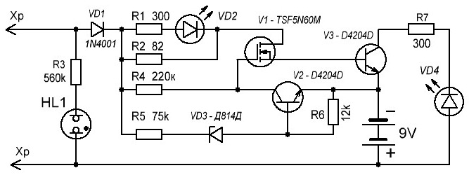
When calling a lansy with a support from zero up to 150 Ohm, a red and yellow light is lit, when a lance is supported from 150 Ohm up to 50 ohm, only a yellow light is lit. When a voltage of 220-380V is applied to the probes, the neon lamp is switched off, and the light emits lightly.
A probe of beatings on three transistors, at the exit station all transistors are closed, the probe probes are open. When the voltage probes of positive polarity are switched on, through the diode VD1 and resistor R5, go to the gate of the field-effect transistor V1, which vibrates and through the base-emitter transition of the transistor V3 connects with the minus dzherel zhivlennya. Spalahuє svetlodiod VD2. Transistor V3 is also turned on, lighting VD4. When connected to the probe, the support in the range of 150 Ohm-50 kOhm, the light diode VD2 goes out, so that the fault of shunting with resistor R2, based on which is less viable, and the voltage on it is not enough for that light. When applying voltage to the probes, the neon lamp HL1 is switched off.
On the VD1 diodes, a single-voltage rectifier is selected. When the voltage is reached on the stabilizer diode VD3 (12V), the transistor V2 turns on and the voltage transistor V1 closes. Svitlodio lightly twitch. 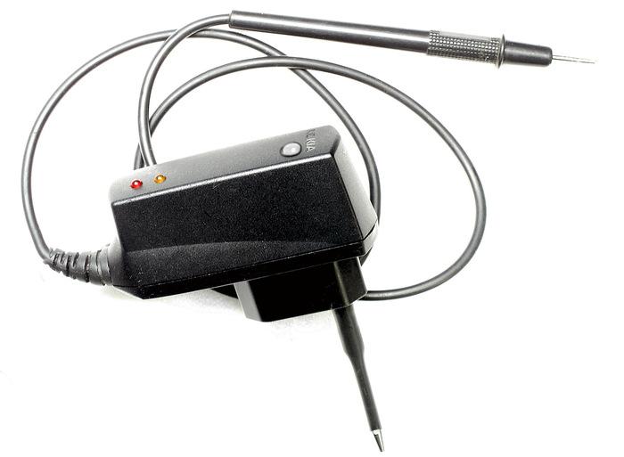 DETAILS: Polyol transistor TSF5N60M can be replaced by 2SK1365, 2SK1338 for pulse chargers and video cameras. Transistors V2, V3 are replaced by 13003A in the form of an energy-saving lamp. Stabilitron D814D, KS515A or analogous to the voltage stabilization 12-18V. Resistors small-sized 0.125 watts. Neon lamp as a twist indicator. Light be-yak, red and yellow light. The diode is rectified, be it with a strum not less than 0.3A and with a reverse voltage greater than 600V, for example: 1N5399, KD281N.
The probe, with proper installation, starts to work as soon as the supply is given. With the adjusted range of 0-150 ohms, you can replace the other one with the selection of resistor R2. The upper boundary of the range is 150 ohm-50 kw to lie in the copy of the transistor V3.
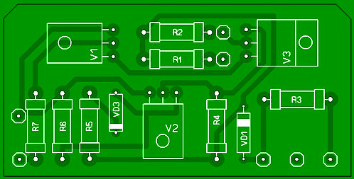
The probe is placed near the insulating housing, for example, at the housing in the form of a charging attachment for a mobile phone. From the front, insert a pin-probe, and from the end of the body, pass through the outer insulation with a pin (or a crocodile).
UNIVERSAL INDICATOR ON MICROSCHEM.
Allows you to signify:
"Phase" wire at power lances and electric lines;
The presence of constant voltage in the interval 10...120V;
The presence of a variable voltage in the interval 10...240V;
The presence of a signal in telephone networks;
The presence of a signal in the broadcasting system;
Spravnіst zapobіzhnikіv;
Comparability of resistors with support 0...100 kΩ;
Comparison of capacitors with a capacity of 0.05 ... 20 microfarads;
Equity of transitions in silicon diodes and transistors;
TTL and CMOS impulse response up to 10 kHz.
In addition, you can know the length of the wires in the wiring harness, as if for an additional voltage of life, and without it. 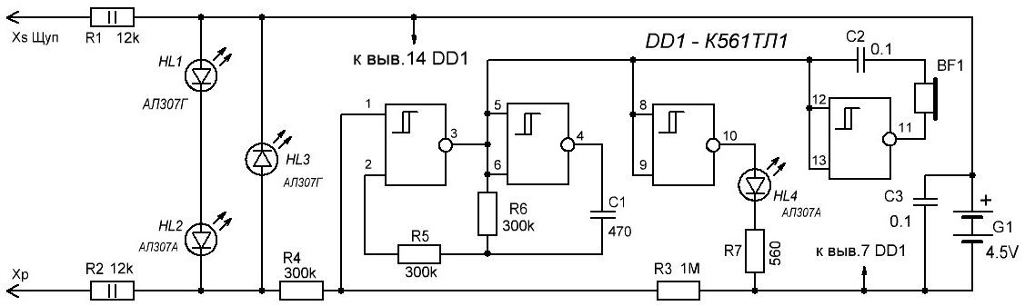
Principal diagram of the indicator.
When the probes are connected, the voltage on the displayed element 1 DD1.1 shows the voltage drop on the successively connected elements HL1, HL2, R3 and R4, which is insufficient for the operation of the DD1.1 trigger. The multivibrator on DD1.1, DD1.2 is not working, the HL4 light diode is not lit. In this mode, the strum, which is powered by the GB1 battery, does not exceed 2 ... 3 μA, which allows the indicator to do without the vibration of life.
In the "promotion" mode, when the probes are muted, the input stream of the lancet passes through resistors R1-R4, the voltage on the output of 1 element DD1.1 moves and starts the multivibrator on the elements DD1.1, DD1.2. From the pulse multivibrator with a pulse frequency of close to 3 kHz, there is an element DD1.3 - a buffer buffer for the HL4 light diode. The cream of light indication of the multivibrator's robot, in contrast to BF1, is carried out in the same way and sound signalization, which is to increase the amplitude of the switching signal between two inverters - DD1.4 and DD1.1.
The supply of a constant voltage of 10 ... 120V to the input of the indicator causes the glow of the light diodes HL1, HL2, and with polarity, which is reversed at the inputs, - HL3. With the increase of the controlled voltage, the brightness of their light, pomit on the eye already over 10V, grows. When controlled by an indicator of a variable voltage of 10 ... 120V with a frequency of 50 Hz, the light of all light diodes HL1 -HL4 is visible, and audibly, the presence of a voltage with a frequency of 50 Hz is noticeable with a characteristic modulation tone of 3 kHz. Moreover, the auditory control is more sensitive, so that modulation is already noticeable at a voltage of 1.5V.
When connected to the probes of the right oxide capacitor, the capacity is 20 microfarads (depending on the polarity of the voltage on the probes), the wine is charged with a lance R1 - R4. With any trivality of the tone signal is proportional to the capacitance of the capacitor, it is overturned - close to 2 seconds per microfarad.
Rechecking the correctness of the conductor diodes and the transitions of the transistors does not require an explanation. It is true that the return stream of the p-n transition of a diode or a transistor is greater than 2 μA, which can cause an audible alarm for whether or not the polarity of the switching on of the conductor transition.
Logical equals TTL and CMOS are indicated with inversion, that is. to the high level, the HL4 light is turned on and the tone signal, and to the low level, the light is turned on and the tone signal.
The advantage of the indicator is that the voltage is tested on the probes, that it does not exceed 4.5V at a stream of 3 μA, it is safe to wind for floor and low-frequency devices.
The circuit has two resistors R1 and R2 moving the safety operation with an indicator, the ratings of these resistors (R1 and R2) are selected according to the boundary value, which is applied to the input of the controlled voltage. So the control of the input voltage up to 380V, with a stream through the light diodes HL1-HL3 close to 10 mA opir resistors R1 and R2 should increase up to 20 kOhm!
When connected to the working equipment, it is necessary to ensure that the internal support of the indicator is less than 24 kOhm.
At the design, it is recommended to use vicorist light HL2 - AL307A, or similar to red lights, and HL4 - with red or yellow lights (for example, AL307D). HL1, HL3 - AL307G or similar to green light. Resistors R1, R2 - MLT-2, other resistors and capacitors - be it small. 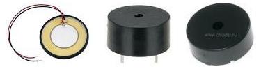
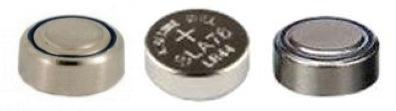
BF1 - whether it's a p'zoceramic vipprominuvach, like a battery of life G1 uses three puddles of "gudzic" elements with a voltage of 1.5V, which are used in calculators, key fobs, lights, etc.
The design and installation of the elements is rich in why to lie in the closed case, you can make an especially small-sized design, after fixing the microcircuit and details for surface mounting. 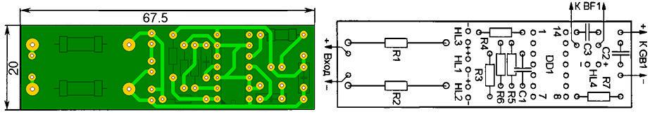
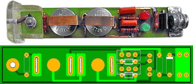
Seat chair available payment option.
The fee is charged for the installation of MLT resistors and capacitors KM-6 (C1) and K10-17. Svіtlodіodi rozmіshchyut zruchnuyu for guarding the mіstsі on the front side of the case.
The plus visnovok of the entrance lancet is attached dotally to the viconat at the looking probe, and the minus one - at the look of the gnuchka dart from the crocodile type on the tip.
With the right details, the adjustment of the fitting does not sound necessary, the Strum of the supply when the inputs are connected is not guilty, but more than 4 μA. Even when the battery is connected, the HL4 indicator will light up and when the windows are switched off, next, choose the light diodes HL1, HL2 with a high limiting voltage, or HL3 with a smaller turning point p-n transition. You can increase the volume of the sound signaling by selecting resistor R6 or capacitor C1, adjusting the generator frequency closer to the frequency that most effectively changes BF1.
AN ADVANCED SCHEME allows you to evaluate the magnitude and sign of the voltage ("+","-","~") in decal ranges: 36V, >36V, >110V, >220V, 380V, and you can also call electric lances, contacts and relay coils, starters, fire lamps, r-n pass, lightly, tobto. Mayzhe everything, with which the electrician most often sticks in the process of his work (crim vimiryuvannya strum).
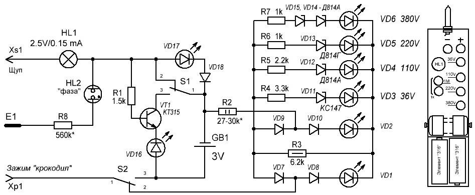
On the diagram of the switch SA1 and SA2, it is shown to the unpressed steel, tobto. in the position of the voltmeter, the magnitude of the voltage can be judged by the number of lights that burn, in the lines VD3 ... VD6, and the lights VD1 and VD2 show the polarity, approximately (recommended) the distribution of the elements on the front panel and in the case is shown on a small scale. Resistor R2 must be made from two or three of the same resistors, connected in series, with a 27 ... 30 kOhm base. Pressing the SA2 jumper changes the probe to a classic ringing tone, tobto. battery and light bulb. If you press the switches between SA1 and SA2, you can change the lancet at two ranges of supports: - the first range - in 1 MΩ and in ~ 1.5 kOhm (light VD15); - another range - from 1 kOhm to 0 (light VD15 and VD16). Stabilizers can be filled with small-sized imported products. Batteries (type "316") serve more and more.
The probe can be supplemented with a "phase" indicator (HL2, R8, pin E1), which will be darker during lighting repairs.
Options for the hull to lie down in the size of different parts. It is better to put the jumpers on the different sides of the payment, even if there will be fewer pardons when you coristuvanni. Most of the pardons are in the fact that, without having changed at the current of the voltage, into a kind of lance, the pressure is on for a call, when the HL1 lamp burns out, playing the role of a protector in this moment. In this rank, when working on non-powered lancers, you need to be careful and respect that the rules of safety technology are respected.
PROBE FOR THE ELECTRICIAN.
The first step is to proceed to work with a probe, the circuit of which is aimed at an offensive little one, it is necessary to charge the storage capacitor C1. For this, just for a few seconds, insert the probe probes into the socket.
If you want to light the LED2 - LED6 light, it will show that the probe is correct and the voltage is 220V. 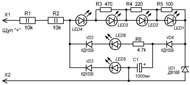
At the process of robotic ignition of light-emitting diodes, it is necessary to confirm the presence of such voltages:
LED4 - 36V;
LED3 - 110V;
LED2 - 220V;
LED1 - 380V.
Light LED5 vikorisovuetsya for prodzvonyuvannya (close to the sound of uninterrupted light), and LED6 to indicate the polarity of the voltage (when the voltage is in the lances of the steady stream).
It is necessary to exercise respect, that it is still a probe, and not a vimiruval accessory, for this the inclusion of light is not clear, but quite sufficient. For example, at a voltage of 127V, LED4 and LED3 light up and LED2 and LED1 turn off. Possibly, for more accurate indication, when adjusting, you can choose the supports R1, R2 and R5.
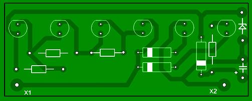
The main elements of the probe are mounted on another board, to change the size of the VD1 and C1 case, they are placed on the board in the main case, the circuit and indicators are removed, and the resistors R1 and R2 are at the auxiliary probe. Capacitor C1 with a vikoristan zener diode D816V is guilty of buti insurance for the operating voltage not lower than 35V. With a yakic capacitor, the charge is saved more for production. The location of the capacitor can be increased. The diodes in the circuit - be it with a maximum voltage of over 50V.
UNIVERSAL PROBE-INDICATOR.
PRESSIONS PRESSIONS SKOKLY WELCOME WITH SVITLODIODIO DIRECTLY SCALLES, VYUZYUGIV ("PRODIVINS"), індикатор смініноїнї інругова індикатора замной комной поданики подиночниковаников коминиє нохідні рудиритрити провитовые мереві, visnant phase ring the lancets for the day of shaving or short chimes. 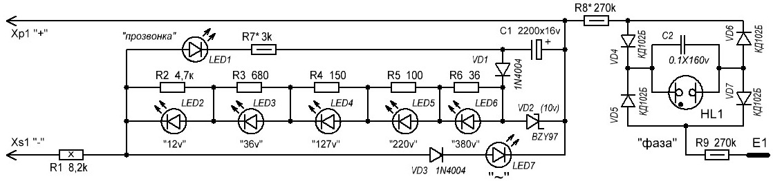
Light scale vikonan on light diodes LED2-LED6 and resistors R2-R6, which shunt the light diode, and can five gradations of standard voltages. The work of the scale is based on the ignition of a light-emitting diode with a drop in voltage on the resistor, which is shunted, close to 1.7V. Lantsyug VD3, LED7 serve to indicate the variable voltage on the probe probes, as well as the return, equal to the polarity of the constant voltage indicated on the diagram.
The conductivity control unit is made up of an accumulative capacitor of equal high capacity C1, a charging port VD1, VD2 and an indicator switch R7, LED1. When the probes are connected for a few seconds to the voltage, the capacitor through the VD1 diode is charged in the voltage, which falls on the zener diode VD2. The sampler is ready before the "prodzvonyuvannya" Lanceugiv.
Just like the probes are stuck on the right lancet, the discharge stream of the capacitor will flow through the new one, resistor R1, LED1 light diode and resistor R7. Svіtlodiod ignite. In the world of discharging a capacitor, the brightness of the light is falling. The indicator of the phase signal picks up behind the circuit of the relaxation generator, having touched the finger of the E1 sensor, with the probe + touch the phase signal. Directed by diodes VD4, VD5, the voltage is charged by capacitor C2. If the voltage is on the new reach of the song value, the neon lamp HL1 is sleeping. The capacitor is discharged through it, the process is repeated.
Light diodes are assigned on the scheme or their out-of-the-box analogues, for example, L-63IT, depending on close parameters, and LED1 - for maximum light output at low struma. The replacement of the zener diode BZY97 (10V) indicated on the diagram can be replaced by D814B and KS168. Capacitor C1-K50-35 or yoga zakordonny analogue. Resistors R2-R9 - MLT with a low intensity, R1 - PEV, C5-37 with an intensity of at least 8W (you can install six series-connected resistors MLT-2 with a support of 1.3 kOhm).
The design can be built around two probes made of dielectric material, connected between themselves with a wire rod at the underwire insulation, protected by a voltage of at least 380V. The main probe, on which placement of the indicator and the additional resistor R1 in which placement. The robot works in all modes without any noises and without an internal element of life. Feelers can be sharpened tips with a diameter of 3 and a length of 20 mm.
As long as all the details are correct and correctly mounted, the probe can be torn apart. It is possible to add a resistor R7 to reach a clear fire LED1 of the light (when connected between the probes of the resistor with a support of 300 ... 400 Ohm). Ale, it’s significant to change the yogo opir not a trace, the shards of the same viklkaє shvidky discharge of the accumulative capacitor. And in order to reach the clearly visible spalahs of a neon lamp, add the resistor R8.
If you often have to control the performance and repair the various attachments, de zastosovuyutsya for the values (36v, 100v, 220v and 380v) of constant and changing voltages, the proponation probe is more robust, it is not necessary to carry out a change in voltage control. A VARIANT of such a probe on two-colour light-emitting diodes, a kind of "pro-ringing" lansy, allows you to visually determine the type of constant or variable voltage and approximately estimate its value in the interval of 12 to 380V, representations on the stepping baby. 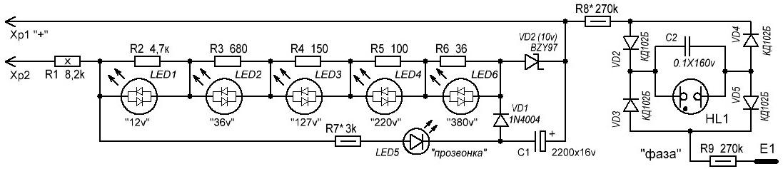
Scheme to replace the scale with two-color LED1-LED5 LEDs, a phase signal indicator on a neon lamp HL1 and a "call" - an indicator of the conductivity of an electric stake.
For vikoristannya, I will add a "pro-call", it is necessary to charge the storage capacitor C1 in front. For this input I will add on 15 ... 20 s, they are connected to a measure of 220V, or to a constant voltage of 12V and more (plus for the Xp1 plug). ). With a little connection to a controlled lance, as a rule, the capacitor is discharged through a new one, a resistor R7 and a light diode LED6, which will light up. To carry out the re-testing for a short time, charge the capacitor for a sprat of re-testing, after which the charging of the capacitor should be repeated. For indication of the input voltage, I will add - the pin Xp1 and Xp2 (for the help of a flexible insulated rod) are connected to the control points. Fallow in the difference of potentials of these points through the resistors R1-R6 and the zener diode VD1 flows through the strum. With an increase in the input voltage, increase and strum, to increase the voltage on the resistors R2-R6. Lights LED1-LED5 fire like a spell, signaling the value of the input voltage. The ratings of the resistors R2-R6 are chosen so that the LED lights up when under pressure:
LED1 - 12V and more,
LED2 - 36V and more,
LED3 - 127V and more,
LED4 - 220V and more,
LED5 - 380V or more.
Depending on the polarity of the input voltage, the color of the light will be different. What is on pin xp1 plus what is nest xs1. svetlodiodi burn with a red color, like a minus - green. With a change in the input voltage, the color of the candle is yellow. It should be noted that if the input voltage is changed or negative, the LED6 light can also be lit.
In the phase indicator mode, the wire in the least of the inputs (Xp1 or Xp2) is connected to the controlled lance and sticks with the finger of the E1 sensor, as a result of which the lance is connected to the phase wire of the neon indicator lamp to light up.
In the stasis circuit: constant resistors R1 - PEV-10. reshta - MLT, C2-23. capacitor - K50-35 or imported, diode KD102B can be replaced by any diode from the 1N400x series, stabilitron KS147A - by KS156A, replacement of two-color light-diodes can be replaced by two different colors of light-string, including a pair.
If it is important that the light of a different color of the light is affected by different values of the direct voltage, then the thresholds of their inclusion for the different polarity of the input voltage will not be the same.
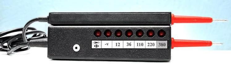
Svetlodio LED1-LED5 and neon lamp HL1 roztashovuyut in a row, so that it was good to see. The Xp1 probe is a metal pin, it is placed at the end of the case at the end, Xp2 is an additional probe, in which the R1 resistor is placed, connected to the main flexible case with a wire with good insulation. Like the E1 sensor, it is possible to twist the screw, stowing on the body of the attachment.
PRODUCTION PROBE - VOLTAGE INDICATOR.
To finish a handy attachment, by which you can change the integrity of the line and the presence of both constant and changeable voltage, building to help the electrician in yoga robots. Scheme є pіdsilyuvachem stіyny strum on transistors VT1, VT2 with the exchange of basic strumіv resistors R1-R3. Capacitor C1 creates a lance of a negative turning signal along the change stream, which turns off the warning indication of the call. Resistor R4 in the stake of the VT2 base serve to install the necessary inter-wiring support, R2 between the strum when the probe works in the lances of the replacement and permanent strum. Diode VD1 rectifies the change strum. 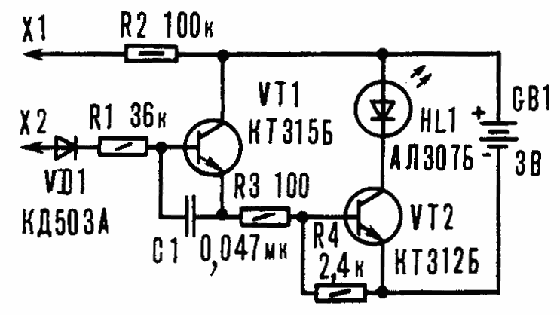
At the output station, the transistors are closed, and the HL1 light diode does not light up, but if the probes are connected at once, or connect them to the right electric lance with a support of no more than 500 kOhm, the light is ignited. The lightness of the yogo light is to lie down under the support of the lansyug, which is overturned - the more it is, the smaller the lightness.
When the probe is connected to the lance of the changeable stream, the transistors are positively turned on, and the light is switched off. Well, the voltage has become, the light will light up, if there is a “plus” on the X2 probe.
At the attachment, you can fix silicon transistors of the KT312, KT315 series with any letter index, with the values of P21e and 20 to 50. Diode VD1 is shorter to install silicon brand KD503A or similar. Svetlodiod type AL102, AL307 with a pressure seal 2-2.6V. Resistors MLT-0.125, MLT-0.25, MLT-0.5. Capacitor - K10-7V, K73, or else small-sized. To live near two elements A332.
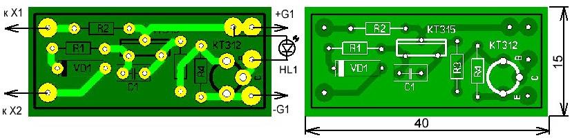
The adjustment of the attachment is more convenient to install on the timing board, by turning on the resistor R4 from the circuit. Before the probes, add a resistor with a support of about 500 kOhm to install the upper inter-wiring support, with which the light diode is guilty of falling. It won’t happen, the transistors need to be changed to other ones, with a larger coefficient h21e. After lighting up the light with the selection of the R4 value, reach the minimum light on the chosen border. If necessary, it is possible to add other inter-wiring supports, changing them for an additional switch. Probe X2 is fastened to the body, and X1 is connected with an attachment with a cable wire, the rest can be removed from the collet olive or vikoristovat ready-made avometer.
ABOUT A ROBOT WITH A BUTTON. The correctness of diodes and transistors is checked by the method of p-n junction support alignment. Vidsutnіst svіtіnnya vkazuє on the urvische of the transition, and as it is, the transition of penetrations. When connected to the probe of the right capacitor, the light will sleep and then go out. In another situation, if the capacitor breaks or may have a great turn, the light will burn steadily. In this way, it is possible to reconsider capacitors with ratings of 4700 pF and more, moreover, the valority of spalachs should be deposited in the vimiryuvanoї єmnostі - chim won more tim, the light was burning longer.
In case of overturning of electric coils, the light is less likely to burn in the fall, if the stench may be less than 500 kOhm. If the value is changed, the light is not lit.
The presence of a variable voltage is determined by the lights of the light. With a constant voltage, the light is less likely to burn in the fall, if there is a "plus" of the voltage on the X2 probe.
The phase is carried out in the following way: take the probe XI in your hand, and the X2 probe is used to suck the dart, and as the light is on, it means that this is the phase of the wire. At the sight of the indicator on the "neonci", there are no pardons for the appearance of the bells.
Vikonati phasing is also not very important. As if when the probe is torn by a dart with a strum, the light shines, it means that the probes are on different phases of the fence, and for the presence of the light - on one and the same.
Opir іzolyatsiї elektropriladіv pervіryayut in this way. With one probe, darts are sucked, and with the other one, the electric appliance. If at any time the light is on, then the insulation is lower than the norm. The number of days of lighting indicates the correctness of the fixture. 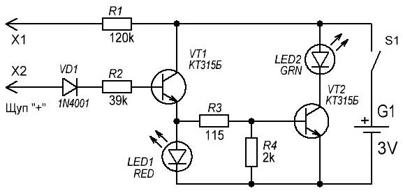
Three changes in the forward scheme, which works in the coming order: When calling: close the probes between themselves with a green light (with these ratings of the scheme, "ring" the lances with a support of up to 200 kOhm).
For the presence of the voltage in the lance, the insult of the light of the green and the red at the same time: the probe is working, as an indicator of the constant voltage of the 5V to 48V and the change of up to 380V, the reception is the light of the red light of the day at 220V, brightness will be higher, lower at 12V. Pratsyuє tsey device in the form of two batteries (tablets), zberіgayuchi pratsezdatnіst protyag kіlkoh rokіv.
UNIVERSAL PROBE Significantly easier search for malfunctions during the repair of various radio equipment, with the help of which you can check the electrical equipment and other elements (diodes, transistors, capacitors, resistors). Vіn dopomozhe to change in the presence of constant or changeable voltages from 1 to 400V, to determine the phase and zero wires, to change the windings of electric motors, transformers, chokes, relays, magnetic starters and inductances.
In addition, the probe allows you to reverse the passage of the signal in the tracts of LF, IF, HF radio receivers, televisions, power supplies, economical, working through two elements with a voltage of 1.5V. 
Scheme of a universal probe.
Attachment of vikonations on nine transistors and is composed of a vibrating generator on transistors VT1, VT2, the operating frequency of which is determined by the parameters of the capacitor C1 and the coil, which is changed by the inductance. By changing the resistor R1, a positive turning point is installed, which ensures the operation of the generator.
Transistor VT3, which works in the diode mode, creates the necessary voltage equalization between the emitter of the transistor VT2 and the base of VT5. On transistors VT5, VT6, a pulse generator is selected, which at the same time, due to the low intensity on transistors VT7, ensures the operation of the HL1 light in one of three modes: the presence of light, the instantaneous light and the uninterrupted light. The mode of operation of the pulse generator depends on the voltage applied to the adjustment of the transistor VT5.
On the VT4 transistors, there is a constant voltage surge, for the help of which the opir and the presence of the voltage are checked. The circuit on transistors VT8, VT9 is a trigger multivibrator with a working frequency of about 1 kHz. The signal to avenge the harmonics is harmonics, so it can be distorted as cascades of low frequencies, and th IF, HF.
Krіm assignments on the circuit transistors VT1, VT2, VT4, VT7 can be of types KT312, KT315, KT358, KT3102. Transistors KT3107V can be replaced by any KT361, KT3107, KT502. Transistor VT3 can be from the KT315 series. The replacement resistor R1 should be set with a logarithmic characteristic "B" or "C". The largest canopy of the parameter is due to appear when the engine is positioned to the right after the scheme. Dzherelo zhivlennya - two galvanic elements of standard size AA with a voltage of 1.5V.
The board and batteries are placed at the plastic case in the same way. A change resistor R1, jumpers SA1-SA3 and a light diode HL1 are installed on the top cover.
Correctly choosing one of the correct details, the probe is repaired immediately after the supply of life pressure. If in the extreme right position of the motor of the resistor R1 and when the probes X1, X2 are connected, the light diode is lit, then it is necessary to change the resistor R4 (more light opir), so that the light diode goes out.
When the voltage is changed, the support is up to 500 kOhm, the correctness of transistors, diodes, capacitors is 5 nF ... 10 μF and the assigned phase signal switcher SA1 is installed at the “Probe” position, and SA2 - at the “1” position. The presence of a variable voltage is determined by the lights of the light. At a constant voltage of 1 ... 400V, the light will only shine in that moment, if the voltage is on the probe X1 ¾ "plus". The correctness of diodes and transistors is checked by the method of p-n junction support alignment. The presence of the light of the light of the light indicates on the passageway. If it’s out of the way, then the passage of penetrations. When connected to the probe of the right capacitor, the light will burn, and then it will turn off. As a capacitor of penetrations, otherwise it may have a great turn, the light will constantly shine. Moreover, the trivality of spalahs lie in the vimiryuvanoї єmnostі: the more it is, the more the light shines, and navpaki. The phase is defined as follows: take the X2 probe by hand, and push the rod with the X1 probe. Yakshcho svіtlodiod svіtitsya, tse i є phase provіd merezhі.
When reversing the coil with an inductance of 200 μH ... 2 H and a capacitor with a capacity of 10 ... 2000 μF, the jumper SA1 is installed at the “Probe” position, and SA2 - at the “2” position. When a reference coil is connected to the inductance and installation of the motor R1, the light blinks at the same position. If in the winding, which is reversed, if the turns are short, then the light will shine; if in a winding є urvische, then the light does not shine. Re-verification of capacitors with a capacity of 10...2000 uF is similar to the above-described re-verification.
When the probe is changed, the signal generator of the SA1 jumper is installed at the "Generator" position. Probe X2 is connected to the "mass" I will attach, and probe X1 - to the main point of the circuit. As a consequence, with the X1 probe, connect an earphone, for example, TM72A, you can make a sound “probing” of electric lances.
The next step is to indicate that at the time of re-wiring of the windings of transformers with a great coefficient of transformation, the probe should be connected to the winding with the largest number of turns.
SIMPLE PROBE-INDICATOR.
Regardless of the size and availability of digital measuring devices (multimeters), radio amators for checking the visibility of the voltage and the correctness of various lances and elements are often blocked by simple indicator devices, which are called probes. For the help of this probe, you can check the presence of the voltage in the controlled lancet, determine its appearance (constantly or change), and also conduct a "calling" of the lancets for correctness. 
The scheme of the attachment is shown in fig. 1 Light-emitting diode HL2 indicates presence at the input (plugs ХР1 and ХР2) of constant voltage polarity. If there is a positive voltage on the XP1 plug, and a negative voltage on the XP2 plug, through the streak resistor R2, the VD2 diode, the VD3 zener diode and the HL2 light diode flow through the strum, then the HL2 light diode shines. Moreover, the lightness of the yogo light lies in the input voltage. With the reverse polarity of the input, the voltages of the vents do not shine.
The HL1 light indicator shows the presence at the input of the device of the changeable voltage. Vіn connections through the capacitor C1 and resistor R3, which surrounds the stream, the diode VD1 protects the light diode from the minus wave of the changeable voltage. One hour with light HL1 light and HL2. Resistor R1 serve to discharge the capacitor C1. The minimum voltage that is indicated is 8V.
As a dzherelo constant voltage for the mode of "dialing" the conduit wires of the ionistor C2 of high capacity. Before carrying out the verification, it is necessary to charge yoga. For this attachment, connect up to 220V for approximately 15 quills. The ionistor is charged through the R2, VD2, HL2 elements, the voltage on the new one is surrounded by a VD3 zener diode. After that input, I will attach it to the lancet, which is checked, and press on the SB1 button. As a guide, through the new one, the contacts of the button, the HL3 light diode, the resistors R4, R5 and the fusible insert FU1 will leak a jet and the HL3 light diode will light, signaling about the problem. The energy reserve in the ionistor is enough for the uninterrupted light of the light source is close to the 20th century.
The intermediate diode VD4 (the voltage of the voltage does not exceed 10.5V) together with the fusible insert FU1 protects the ionistor from a high voltage at the drop, so that when controlling the input voltage, or charging the ionistor, the button SB1 will be pressed. The melting insert will burn out and it is necessary to replace it.
At the attachment, the resistors MLT, C2-23, capacitor C1 - K73-17v, diode I N4007 can be replaced by diodes 1N4004, 1N4005, 1 N4006, zener diode 1N4733 - by 1N5338B. All parts are mounted on a mock-up mounting plate due to wired installation.
PROVISION OF THE TELEPHONE CAPSULES.
If someone has a telephone capsule (earphone) TK-67-NT lying around in the state for use in telephones, or similar with a metal membrane and may be connected sequentially in the middle of two coils, then on this base you can choose the simplest sound "ringing". 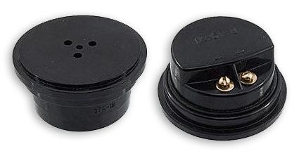
It’s true, for this earmuff it’s possible to add a little more - to sort out and separate the cats, having made the visnovkas in the skin of them. All details can be placed in the middle of the telephone capsule under the membrane of the coil. When the phone is folded, it transforms into a miraculous sound generator, which can be twisted, for example, for rechecking other circuit boards for switching tracks between itself, or for other purposes - let's say, like a sound indicator of turns.
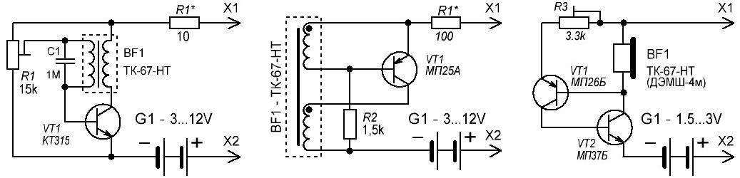
Variants of schemes are shown a little.
The basis of the probe is a generator with an inductive turn signal, picking up transistors VT1 and telephones BF1. On the guidance circuit, the voltage of the battery (battery) is set to 3V, but you can also change it (from 3 to 12V) by selecting the strumming resistor R1. Like VT1, it is possible to vikoristovuvati practically whether it is a low-power (rather german) transistor. As soon as a transistor appears by hand due to the N-P-N conductor, then it will be possible to change the polarity of the increase in the life. If the generator does not start when it is first turned on, it is necessary to replace the coils of one of the coils with a few pieces. For greater volume to the sound, the frequency of the generator should be chosen close to the resonant frequency of the telephone, as it is possible to increase the gap between the membrane and the core.